
Subscribe to Our Youtube Channel
Summary of Contents for Accutron PRO
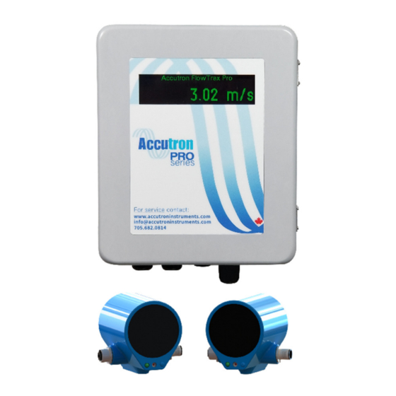
- Page 1 Accutron Pro Technical/Operations Manual PRELIMINARY V 0.0.4 For more information on our products visit www.accutroninstruments.com Contact us by email: info@accutroninstruments.com Or by Phone: 705-682-0814...
- Page 2 PLEASE NOTE: This Manual is a work in progress and is being revised regularly. It may not accurately reflect the most up-to-date systems. If you require any assistance in configuring your new Accutron Pro Device, please call our technicians at +1-705-628-0814.
-
Page 3: The Manual
The Manual Refer to this manual for proper installation, operation, setup and maintenance of the Accutron Pro. Special attention must be followed to warnings and notices highlighted from the rest of the text to ensure it will stand out. Warning: Failure to oblige with the necessary precautions can result in death, serious injury, and/or considerable damage to the product. -
Page 4: Table Of Contents
Calculating the Baseline ..........................12 Calculations ............................. 12 Mounting the Transmitter Box ........................13 Navigating the Menu ..........................13 Menu Options ............................. 13 Section 7: Accutron Pro Web Interface ...................... 17 The Dashboard ............................18 Settings................................ 18 Setup ............................... 18 Networking.............................. 18 Analog Output ............................ -
Page 5: Introduction
Industrial DCS as well the World Wide Web. The Accutron Pro is designed to be easy to use and intuitive in its application. It provides a host of “most wanted features” in a single stand-alone product. -
Page 6: Section 1: General Information
Information about your Accutron Pro When you first receive your Accutron Pro device, ensure you record the following information shown below. If you need to contact Customer Service, this information will allow us to provide you more efficient service. This information is located under the Lid of the Accutron Pro. - Page 7 Section 2: Specifications CPU: ARM® 32bit MCU Connections: Pluggable Screw terminal blocks Input Power: Terminal blocks: 20 VDC to 48 VDC, 6 watts typical PoE: 48V IEEE 802.3af, Mode A & B compatible Interfaces: Ethernet: Modbus TCP, Ethernet I/P 2x RS-485: Modbus RTU Accutron Device Bus: Airflow sensors, Temperature/humidity sensors, Display...
-
Page 8: Section 3: Communication & Power Wiring Diagram
Section 3: Communication & Power Wiring Diagram AC Power Input DC Power Input P a g e... - Page 9 P a g e...
- Page 10 Connection Entry Diagram Bottom View P a g e...
-
Page 11: Section 4: Inside The Enclosure
Section 4: Inside the Enclosure LED Indicators: Power and 4 user settable LEDs Micro SD card: The Micro SD card can be inserted and removed from underneath the lid of the enclosure. Navigation Buttons: Press and hold the center navigation button to enter the menu. Color Display: Reboot button: Reboots device. -
Page 12: Section 5: Drawings & Dimensions
Section 5: Drawings & Dimensions Transmitter Enclosure P a g e... - Page 13 Accutron Pro Module Power LED1 LED2 LED3 LED4 Width 4.395" Accutron Pro (111.63mm) PN: ACC-PRO www.accutroninstruments.com 705.682.0814 Flow Pro Module 4-20mA Out Dry Contact Accutron Bus + A B - Length 4.236" (107.59mm) Top View 1.775" (45.09mm) Height 2.400" (60.96mm) 1.4"...
- Page 14 Drift Sensor Mount Drift Sensor 10 | P a g e...
-
Page 15: Section 6: Installation
Section 6: Installation Note: The examples below refer to the drift sensors, but the same methods apply for all sensor installations (fans, ducts, tunnels, etc.) When mounting the transducers to the wall, it is recommended that one be installed near the ceiling of the drift and the other located downstream near the bottom of the drift (figure 7). -
Page 16: Calculating The Baseline
Once the mounts are installed, thread the sensors onto the mounts and point them at each other using pan/tilt adjustment on the mount. Once power is run to the unit these sensors can be aligned properly using the laser alignment found in the configuration menu of the transmitter. -
Page 17: Mounting The Transmitter Box
Navigating the Menu The Accutron Pro will boot up as soon as it receives power. Under the lid, the Pro has a keypad used for navigating the menus. On initial bootup, the Accutron Pro will configure itself with default settings. - Page 18 • Display Mode – chose to display velocity or volumetric. • Flow Direction – if the airflow is negative, use this to make it positive • Moving Average Size – used the smooth out the readings Transducer Setup • Clear Tilt Alarm – Used to clear system of any tilt alarms. •...
- Page 19 Modbus RTU Settings – This menu allows you to configure the Modbus RTU settings of your Accutron Pro Device • Baud Rate – Allows you to set the Modbus Baud Rate from 110 to 115200 • Slave ID - Set the Slave ID of the Modbus device •...
- Page 20 TCP Settings - This menu allows you to configure the Modbus TCP settings of your Accutron Pro Device • Slave ID • TCP Port Exit – Selecting this will return you to the Accutron Pro Home Screen 16 | P a g e...
- Page 21 17 | P a g e...
-
Page 22: Section 7: Accutron Pro Web Interface
The units of the values are based on whatever the device was set to in the setup menu. There is an option to “Clip to range”. When this is selected (the box is checked) the Pro will output the min and max mA values when the variables are at their min/max or beyond. -
Page 23: Alarms And Relays
This page is used to configure Modbus RTU & TCP Slave settings. The Modbus Register Map can be found on this page. More details are provided in the section 9 below. Modbus Master This page is used to configure the Pro as a Modbus Master. More details are provided in the section 8 below. Firmware Update This page allows you to upload firmware updates to either your Pro System or Pro Transducers remotely. -
Page 24: Section 8: Modbus Master Settings
Section 8: Modbus Master Settings Click the Settings button to expand the menu. Click Modbus Master. Here you can configure your devices Modbus RTU Master settings such as baud rate, data pits, stop bits and parity bits. Click Add New Device to begin adding new Modbus Slave devices. -
Page 25: Section 9: Modbus Slave Settings
Modbus TCP Port: TCP port number, default is 502 Modbus TCP Slave ID: Slave ID, default is 1. Modbus Slave Register Map (RTU&TCP) shows what each register on the Accutron Pro is mapped to. 21 | P a g e... -
Page 26: Modbus Register Map
Modbus Register Map Base unit mapping Additional Climatrax probe 22 | P a g e... - Page 27 System Wiring Diagram 23 | P a g e...
Need help?
Do you have a question about the PRO and is the answer not in the manual?
Questions and answers