Table of Contents
Advertisement
Quick Links
Advertisement
Table of Contents

Summary of Contents for bwa MR36
- Page 1 3G/UMTS (HSDPA) router MR36 USER GUIDE Version: 30-Jan-2008...
-
Page 2: Table Of Contents
2.5. Antenna Connection 2.6. SIM Card Reader 2.7. Power Supply 2.8. Technical parameters 2.9. Description of individual components of MR36 2.9.1. UMTS module 2.9.2. Control microcomputer 2.10. User interfaces (Connectors) 2.10.1. Connection of the PWR Supply Connector 2.10.2. Connection of the Port1 Connector – RS232 2.10.3. - Page 3 Danger – important notice, which may result in feedback on user’s safety or devices function. Attention – notice on possible problems, which can come to in specific cases. Information, notice – information, which contents useful advices or interest notice. © BWA Technology GmbH...
-
Page 4: Safety Instruction
SAFETY INSTRUCTION 1. Safety instruction Please, observe the following instruction: The communication module MR36 must be used in compliance with any and all applicable • international and national laws and in compliance with any special restrictions regulating the utilization of the communication module in prescribed applications and environments. -
Page 5: Description Of The Mr36 Router
SIEMENS which enables data transfers using HSDPA/UMTS/EDGE/GPRS GSM, GPRS and UMTS technologies. Primarily, the MR36 router expands the capabilities of the HC15 module by the option of connecting more PCs by means of the built-in Ethernet interface. In addition, the firmware... -
Page 6: Hsdpa Technology (High Speed Download Packet Access)
• 2.5. Antenna Connection The whip antenna is connected to MR36 using an FME connector on the back panel. External whip antenna: 2.6. SIM Card Reader The SIM card reader for 3 V and 1.8 V SIM cards is located on the front panel of the modem, eventually inside router in case of adapter for the second SIM card. -
Page 7: Power Supply
SIM card 2.7. Power Supply MR36 requires +10 V DC to +30 V DC supply. The protection against reversal of polarity without signaling is built in the modem. The power consumption during receiving is 1W. The peak power consumption during data sending is 3.5W. -
Page 8: Technical Parameters
MR36 User Manual 2.8. Technical parameters HSDPA/UMTS/EDGE/GPRS module SIEMENS HC15 Complies with standards 3GPP TS 51.010–1, 3GPP TS 34.121, 3GPP TS 34.123–1, 3GPP TS 34.123–3, ETSI EN 301 511 V9.0.2, ETSI EN 301 489–1 V1.4.1, ETSI EN 301 489–7 V1.2.1, EN 60950–1 ed.2:2006,... -
Page 9: Description Of Individual Components Of Mr36
2.9.2. Control microcomputer The core of the MR36 router is a 32-bit microprocessor Motorola MCF5329 with 16 MB RAM, 4 MB FLASH EEPROM, serial interface RS-232 and an Ethernet interface 10/100 Mbit/s. The microcomputer is connected to the HC15 OEM module through the USB interface and controls the communication via HSDPA/UMTS/EDGE/GPRS UMTS. -
Page 10: User Interfaces (Connectors)
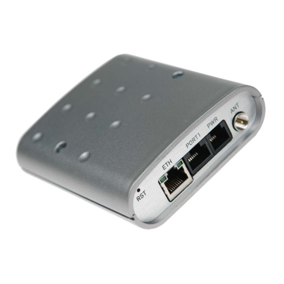
MR36 User Manual 2.10. User interfaces (Connectors) On the back panel of MR36 the following connectors are located: • one RJ12 connector (PWR) – for connection of the power supply adapter, • one RJ45 connector (ETH) – for connection into the local computer network, one RJ45 connector (PORT1) –... -
Page 11: Connection Of The Port1 Connector - Rs232
DC supply voltage (10 to 30 V) GROUND – signal ground Receive Data Carrier Detect Transmit Data ATTENTION! If MR36 is connect to DiREX-Pro SubD connector, please unplug external power supply from PWR connector!!! 2.10.3. Connection of the ETH Connector Panel socket RJ45. Signal... -
Page 12: Technical Specification Of Optional Port1
Off ....... the network cable is not connected 2.13. Putting into operation Before putting the MR36 router into operation it is necessary to connect all components needed for the operation of your applications and the SIM card must be inserted (the modem is off). -
Page 13: Mechanical And Built-Up Size And Recommendation
MR36 User Manual 2.14. Mechanical and built-up size and recommendation For majority applications with built-in modem in switch board it is possible recognize two sort of environment: no public and industry environment of low voltage with high interference, • public environment of low voltage without high interference. - Page 14 MR36 User Manual singles cables we recommended to bind to the one's bunch according to next picture, • for this way guidee cables reads this limitation: length of the bunch (combination of power supply and data cables) can be maximum 1,5 m, if length of data cables overreached 1,5 m...
- Page 15 MR36 User Manual circuitry of modem is on the following pictures. • © BWA Technology GmbH...
-
Page 16: Configuration Setting
MR36 User Manual 3. Configuration setting Attention! If the SIM card isn’t included in router MR36, it is impossible router MR36 operate. Included SIM card must to have activated HSDPA/UMTS/EDGE/GPRS UMTS transmissions. The SIM card include when the router MR36 is switch off. - Page 17 MR36 User Manual TX packets – transmit packets, errors – number of errors, dropped – dropped • packets • collisions – number of collisions • RX bytes – total number of received bytes, TX bytes – total number of transmit bytes •...
-
Page 18: Dhcp Status
MR36 User Manual 3.2. DHCP Status Information about IP addresses which was allotted of DHCP server to MR36; it is possible find in menu in sum DHCP: lease 192.168.1.2 (generally IP address) – assigned IP address • • starts – information about time of assigned IP address ends –... -
Page 19: Dyndns Status
MR36 User Manual 3.5. DynDNS status DynDNS up - dating entry result on server www.dyndns.org it can be call - up option DynDNS item in menu. 3.6. System Log In case of any problems with PPP connection it is possible to view the system log by pressing the System Log menu item. -
Page 20: Ppp Configuration
MR36 User Manual The changes in settings will apply after pressing the Apply button. The DHCP server assigns to the connected clients IP addresses from the defined address pool, IP address of the gate and IP address of the primary DNS server. It is important to don´t overlap ranges of static engaged IP address with address allotted by the help... -
Page 21: Nat Configuration
Default Server item it is possible to put the MR36 router into the mode in which all incoming data from UMTS will be routed to the computer with the defined IP address. If the Enable remote HTTP access field is filled in, it is maybe configuration of router over web interface. - Page 22 At these configuration it is important to have mark election Send all remaining incoming packets it default server, IP address in this case is device address behind MR36. Connected equipment behind MR36 must have setting Default Gateway on the MR36. At distant PING on IP address of the SIM card matches connected equipment.
- Page 23 (Public port), there this port isn't defined, therefore at check election Enable repote http access it is automatically opens web interface MR36. If this choice isn't check and is check volition Send all remaining incoming packets to default server fulfil oneself connection on induction IP address.
-
Page 24: Gre Tunnel Configuration
MR36 User Manual 3.10. GRE Tunnel Configuration To enter the GRE tunnel configuration, select the GRE menu item. In the window it is possible to define the IP address of the remote side of the tunnel (Remote External IP Address), internal IP address of the local side of the tunnel (Local Internal IP Address), internal... - Page 25 MR36 User Manual To enter the L2TP tunnel configuration, select the L2TP menu item. In the window it is possible to define L2TP tunnel mode (Mode) on ER75i side, in case of client IP address of server (Server IP Address), start IP address in range, which is offered by server to clients...
-
Page 26: Dyndns Client Configuration
PPP connection. Info is possible send on two telephone number. Unit ID is name of the MR36 which it will send in SMS message. Unit ID may to have arbitrary form. -
Page 27: External Port Configuration
MR36 User Manual Behind power up MR36, at introduction telephone number it come SMS in the form of: MR36 (Unit ID) has been powered up. GSM signal strength: -xxdBm, where is GSM signal strength – level signal Behind PPP establishment (PPP connect) it come SMS in the form:... -
Page 28: Change Password
MR36 User Manual Example of external port configuration: ppp0 10.0.0.2 ppp0 10.0.0.1 RS232 192.168.1.1 192.168.1.100 Settings in application on PC: Settings in UR-5 TCP connection on 10.0.0.2:2000 Mode: TCP server Server Address: - Default Gateway 192.168.1.1 TCP Port: 2000 ppp0 10.0.0.2 RS232 ppp0 10.0.0.1... -
Page 29: Setting Inner O'clock
MR36 User Manual In basic setting of router MR36 password is set on default form root. For higher secure of our network we recommended to change this password. 3.17. Setting inner o’clock One - shot setting inner o'clock of the router it can be call - up option Set Real Time Clock item in menu. -
Page 30: Reboot
Total update time lasts for 3 - 4 minutes. During updating of firmware it has to be reservation permanent power supply. We don’t strongly recommended distant update because of blackout PPP connection. 3.22. Reboot To reboot the MR36 router select the Reboot menu item and then press the Reboot button. © BWA Technology GmbH... -
Page 31: Default Settings
MR36 User Manual 3.23. Default settings PPP Configuration 3.23.1. NAT Configuration 3.23.2. © BWA Technology GmbH... -
Page 32: Ipsec Tunnel Configuration
MR36 User Manual IPsec Tunnel Configuration 3.23.3. GRE Tunnel Configuration 3.23.4. L2TP Tunnel Configuration 3.23.5. © BWA Technology GmbH... -
Page 33: Dyndns Configuration
MR36 User Manual DynDNS Configuration 3.23.6. NTP Configuration 3.23.7. SMS Configuration 3.23.8. External Port Configuration 3.23.9. © BWA Technology GmbH... -
Page 34: Possible Problems
Switch log system on and observe where the error turns up. Connection fails on Ethernet or connection isn’t establishing. On ethernet interface of MR36 it is possible switch auto negotiation off and set a rate and duplex by hand. DynDNS not function. -
Page 35: Keeping About Customers
MR36 User Manual RS232 don’t function. It is necessary verify present the expansion port RS232. Verify present the expansion port RS232 in MR36 configuration in menu „external port“, or verify connection locally by the help Telnet-Hyper terminal. L2TP or IPSec isn’t establishing. -
Page 36: Guarantee Claim Guidelines
MR36 User Manual 7. Guarantee Claim Guidelines Dear customer, The product that you have purchased was tested by the manufacturer and, before it was sold, the product’s functions were checked once more by our company’s technician. However if, in spite of the above-mentioned measures, a breakdown of this product occurs during the guarantee period, which makes proper utilization of the product impossible, we ask you to observe the Guarantee Claim Guidelines when asserting a guarantee claim. - Page 37 MR36 User Manual claim by exchanging the object of the guarantee claim for a faultless product, the new guarantee of the product shall expire as follows: 1. After the expiration of a period of 12 months from the date of acceptance of the exchanged product by the customer.
-
Page 38: Guarantee Certificate
Guarantee certificate MR36 – 3G/UMTS router 8. Guarantee certificate Type of the device Serial number Guarantee period (in months) Seller Date of sale Stamp of the seller © BWA Technology GmbH... - Page 39 Guarantee certificate MR36 – 3G/UMTS router Date of reception of the guarantee claim by the seller Number of the guarantee claim report Date of reception of the device into the repair shop Date of completion of the repair by the...
Need help?
Do you have a question about the MR36 and is the answer not in the manual?
Questions and answers