Advertisement
Quick Links
CNC Router Parts
2.2 kW Plug and Play Spindle / VFD System
CRP800 Retrofit Guide
Step 1:
Congratulations on your purchase of the CNC Router Parts 2.2 kW Plug and Play Spindle / VFD
System!
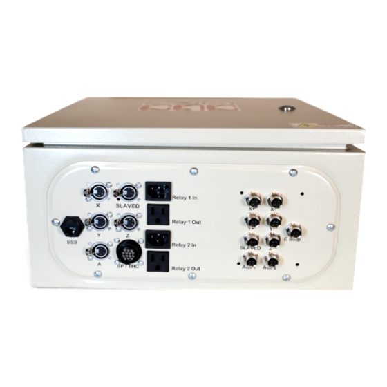
The first step in setting up your Spindle will be to upgrade your current CRP800 Control Unit with
VFD Compatibility. You should have received a 14 pin connector with your Retrofit Kit. (See below)
This connector will be zip tied to separate out the 4 pins used for speed and fault signaling from the
relay wiring. (See Below)
Copyright©2015 CNC Router Parts LLC. All Rights Reserved.
CNC Router Parts
CNC Router Parts
2.2 kW Plug and Play Spindle / VFD System
CRP800 Retrofit Guide
Copyright©2015 CNC Router Parts LLC. All Rights Reserved.
1
Advertisement

Summary of Contents for CNC Router Parts CRP800
- Page 1 Congratulations on your purchase of the CNC Router Parts 2.2 kW Plug and Play Spindle / VFD System! The first step in setting up your Spindle will be to upgrade your current CRP800 Control Unit with VFD Compatibility. You should have received a 14 pin connector with your Retrofit Kit. (See below) This connector will be zip tied to separate out the 4 pins used for speed and fault signaling from the relay wiring.
- Page 2 2.2 kW Plug and Play Spindle / VFD System CRP800 Retrofit Guide To install this 14 Pin connector, first remove the SP/THC port cover on your CRP800 Control Unit. (See below). Next install the 14 pin connector from the back side of the gland plate, with the square plastic flange inside of the Control Unit.
- Page 3 The 14 pin connector must now be wired to the break out board inside of the Control Unit. Install the four pin SUPU connector onto the break out board in the orientation and position shown below. Copyright©2015 CNC Router Parts LLC. All Rights Reserved. CNC Router Parts 2.2 kW Plug and Play Spindle / VFD System...
- Page 4 Note, you may have to crimp down on the QDCs to create a solid connection. Your CRP800 Control Unit is now ready to connect to the VFD via the grey 14 pin cable included with your Spindle and VFD Package.
- Page 5 CRP800 Retrofit Guide Step 2: You may now physically connect your VFD to your CRP800 Control Unit with the supplied 14 pin cable. (See below). The 14 pin male-to-male cable should connect to the female 14 pin connectors on both the control box and the VFD as shown below.
- Page 6 VFD enclosure. If these arrows do not align, the cable will not make a functional connection (see below). Copyright©2015 CNC Router Parts LLC. All Rights Reserved. CNC Router Parts 2.2 kW Plug and Play Spindle / VFD System CRP800 Retrofit Guide Copyright©2015 CNC Router Parts LLC.
- Page 7 Step Low Active must show a red X Step Port set to 2 Copyright©2015 CNC Router Parts LLC. All Rights Reserved. CNC Router Parts 2.2 kW Plug and Play Spindle / VFD System CRP800 Retrofit Guide Copyright©2015 CNC Router Parts LLC. All Rights Reserved.
- Page 8 Port must be set to 2 o Pin Number must be set to 14 o Active Low must show a green check Copyright©2015 CNC Router Parts LLC. All Rights Reserved. CNC Router Parts 2.2 kW Plug and Play Spindle / VFD System CRP800 Retrofit Guide Copyright©2015 CNC Router Parts LLC.
- Page 9 In General Parameters o CW Delay Spin UP Should be 5 Seconds (or greater if you prefer a longer delay) Copyright©2015 CNC Router Parts LLC. All Rights Reserved. CNC Router Parts 2.2 kW Plug and Play Spindle / VFD System CRP800 Retrofit Guide Copyright©2015 CNC Router Parts LLC.
- Page 10 Set Max Speed to 24000 Set Ratio to 1 Copyright©2015 CNC Router Parts LLC. All Rights Reserved. CNC Router Parts 2.2 kW Plug and Play Spindle / VFD System CRP800 Retrofit Guide Copyright©2015 CNC Router Parts LLC. All Rights Reserved.
- Page 11 Set “Acceleration” to 200 Save Axis Settings and then hit “OK” Copyright©2015 CNC Router Parts LLC. All Rights Reserved. CNC Router Parts 2.2 kW Plug and Play Spindle / VFD System CRP800 Retrofit Guide Copyright©2015 CNC Router Parts LLC. All Rights Reserved.
- Page 12 Under “spindle” ensure the PWM box is checked Base Hz must be 100 Copyright©2015 CNC Router Parts LLC. All Rights Reserved. CNC Router Parts 2.2 kW Plug and Play Spindle / VFD System CRP800 Retrofit Guide Copyright©2015 CNC Router Parts LLC. All Rights Reserved.
- Page 13 Once you have input a valid spindle speed, (not rpm or S-ov), Click the “Spindle CW F5” button to turn the spindle on and run it at that speed. Copyright©2015 CNC Router Parts LLC. All Rights Reserved. CNC Router Parts 2.2 kW Plug and Play Spindle / VFD System...
- Page 14 CRP800 Retrofit Guide If you experience any trouble while following this guide, please feel free to contact us at: support@cncrouterparts.com Copyright©2015 CNC Router Parts LLC. All Rights Reserved. CNC Router Parts 2.2 kW Plug and Play Spindle / VFD System CRP800 Retrofit Guide Copyright©2015 CNC Router Parts LLC.
Need help?
Do you have a question about the CRP800 and is the answer not in the manual?
Questions and answers