Advertisement
Quick Links
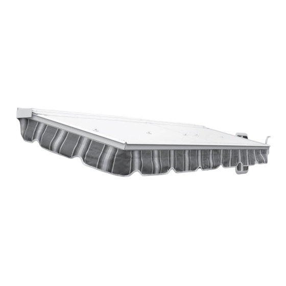
DFSOC-10
Dura-Fold Slide Out Cover
Assembly and Installation Instructions
Read the instructions before starting the job. They explain the steps required
to produce a fi nished product that will meet factory specifi cations.
All references to "Left" and "Right" are while facing the home.
Check the material received.
Safety is important!
Match your shipment with the Bill of Materials.
Wear Safety Glasses and Work Gloves.
If there is a shortage or wrong material,
Follow all safety practices while assembling
call Dealer Service immediately.
and installing this product.
Dura-Bilt Products, Inc. P.O. Box 188 Wellsburg, N.Y. 14894
Dealer Service 570-596-2000 E-Mail info@durabilt.com
DURA-BILT RESERVES THE RIGHT TO CHANGE DESIGN AND/OR SPECIFICATIONS WITHOUT NOTICE.
Advertisement

Summary of Contents for DURA-BILT DFSOC-10
- Page 1 If there is a shortage or wrong material, Follow all safety practices while assembling call Dealer Service immediately. and installing this product. Dura-Bilt Products, Inc. P.O. Box 188 Wellsburg, N.Y. 14894 Dealer Service 570-596-2000 E-Mail info@durabilt.com DURA-BILT RESERVES THE RIGHT TO CHANGE DESIGN AND/OR SPECIFICATIONS WITHOUT NOTICE.
- Page 2 Fasteners Description 1-1/2” OD x 1/4” ID White Bonded EPDM Washer 1/4”Quick Release Pin 1” OD x 9/32” ID SS Fender Washer #10-24 x 1/2” Thumb Screw 1/4”-20 Aluminum Wing Nut #10-24 Aluminum Wing Nut 1/4”-20 x 2” Hex Aluminum Bolt #12 x 1-1/2”...
- Page 3 Component Descriptions “U” Channel Panel Hinge Mounting Rail End Cap (Right Side) Front, Left & Right Trim 1-1/2” x 2-1/2” Header Angle Left Side Opposite Correctly Oriented RV Rail Lock Down Bracket (If Required) Slide Out Roof Panel Important! Because there is no way to know the confi...
-
Page 4: Getting Started
Slide Out Cover. Install the RV Rail above the slide out as far as you can. Dura-Bilt supplies RV Rail with every Slide Out Cover that has the correctly oriented opening for the Mounting Rail. - Page 5 Mounting Rail Installation Note: The RV Rail may be slightly shorter than the Mounting Rail. Note: this product is sold in maximum section widths of 4’ and will be assembled in the fi eld from the supplied components. If it’s necessary to shorten the Slide Out Cover any or all panels can be cut, and extrusions shortened.
- Page 6 Stud Mounting Rail Bottom Leg Mounting Rail 9. If you loosened any fasteners in the RV Rail, tighten them now. First, apply a generous bead of caulking in the cavity between the RV Rail and the side wall of the RV. Also caulk full length of top of the joint of Dura-Fold Mounting Rail and the RV Rail.
- Page 7 Panel and Extrusion Assembly 1. Start by sub-assembling the left panel on the ground. 2. Install a “U” Channel on the left side of the Panel and an “H” Bar on the right side of the Panel. Make sure the assembly is together tight. Note: The “U”...
- Page 8 Panel and Extrusion Assembly 5. Install the next panel, making sure it is tightly together before installing the next three (3) #8 x 1/2” screws as you did in step 4 on the previous page. Install the rest of the panels in the same maner and install a “U” Channel over the right side of the last panel, then install the next three (3) #8 x 1/2”...
- Page 9 Panel and Extrusion Assembly 8. Install Right Trim using three (3) #8 x 1/2” screws. Right Trim 9. Install the Left & Right Front Trims using #8 x 1/2” screws in the pattern shown in illustration below. Top view of Slide Out Cover 10.
- Page 10 Installation of the 1-1/2” x 2-1/2” Header Angle 1. Hold the Slide Out Cover up and extend the RV Slide Out. Locate and mark where the Header Angle is to be attached to the face of the RV Slide Out. The Header Angle should be fl ush with the top of the Slide Out and fi t between the two (2) Valance legs of the Slide Out Cover.
- Page 11 Attachment of Slide Out Cover to Header Angle (continued) Top View of Slide Out Cover 1/4”-20 x 2” Hex Bolt with 1-1/2” Washer Caulk Around 1/4” Hex Bolt Side View of Slide Out Cover Sealing all Seams You are supplied with Sealer Tape (Peel & Seal) to cover the seams in the Mounting Rail, Panel Hinge and Front Trim.
-
Page 12: Install Flashing
Install Flashing You will receive a strip or strips of Flashing (depending on the length of your Slide Out Cover) that are to be inserted into the fl ashing recess on the Mounting Rail. The Flashing comes in 10’ lengths. They are overlapped by a minimum of 1”. - Page 13 Off Season Storage (continued) Note: the views of the Lock Down Bracket below are shown for clarity but for ease of assembly rotate 90 degrees. Side View of Slide Out Cover folded down. Side View of Slide Out Cover folded down showing Lock Down Bracket installation.
- Page 14 Notes Page 13...
- Page 15 Notes Page 14...
-
Page 16: Five Year Limited Warranty
Within the warranty period, to be confi rmed with copy dated bill of sale, Dura-Bilt Products, Inc. will, at its sole option, repair or replace any components which the owner has proven to have failed in normal use. Such repairs or replacement will be made, at no charge for parts, to the original purchaser.
Need help?
Do you have a question about the DFSOC-10 and is the answer not in the manual?
Questions and answers