Philips DCM5090/10 Service Manual
Hide thumbs
Also See for DCM5090/10:
- Quick start manual (2 pages) ,
- User manual (22 pages) ,
- Brochure & specs (3 pages)
Advertisement
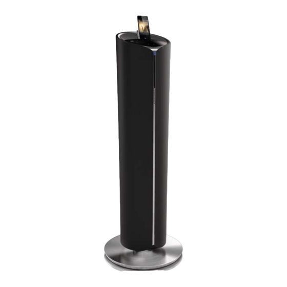
Docking Entertainment System
©
Copyright 2011 Philips Consumer Electronics B.V. Eindhoven, The Netherlands
All rights reserved. No part of this publication may be reproduced, stored in a retrieval system or
transmitted, in any form or by any means, electronic, mechanical, photocopying, or otherwise without
the prior permission of Philips.
Published by SL 1134
BG LE
Printed in The Netherlands
Version 1.0
TABLE OF CONTENTS
PCBs Location & Version Variations ..................................... 1-2
Specifications
fi
....................................................................... 1-3
Measurement Setup ............................................................. 1-4
Service Aids, Service Instruction, etc ................................... 1-5
Software Version Checking ..................................................... 2
Set Block Diagram ................................................................... 3
Set Wiring Diagram ................................................................. 4
Main Board .............................................................................. 5
CD Board................................................................................. 6
VFD/KEY Board ....................................................................... 7
Iphone/Ipod & IR & USB & FM & AUX IN Board .................... 8
Set Mechanical Exploded View ................. ............................. 9
Revision List .............................................. ........................... 10
Subject to modification
DCM5090
Page
CLASS 1
LASER PRODUCT
3141 785 36690
/10
Advertisement

Related Manuals for Philips DCM5090/10


Summary of Contents for Philips DCM5090/10
-
Page 1: Table Of Contents
LASER PRODUCT © Copyright 2011 Philips Consumer Electronics B.V. Eindhoven, The Netherlands All rights reserved. No part of this publication may be reproduced, stored in a retrieval system or transmitted, in any form or by any means, electronic, mechanical, photocopying, or otherwise without the prior permission of Philips. - Page 2 1 - 2 PCBS LOCATION IPHONE/IPOD DOCKING BOARD VFD/KEY & LED BOARD HDD BOX IR BOARD USB JACK BOARD CD BOARD CD MECH FM ANT BOARD SWITCHING TRANSFORMER MODULE VERSION VARIATIONS Type /Versions: DCM5090 Service policy Board in used: MAIN BOARD CD BOARD USB JACK BOARD VFD/KEY/LED BOARD...
- Page 3 Speakers Speaker 6 ohm + 3 x 6 ohm Rated Output 200 W Impedance Power Speaker Drive 5.25”woofer + 3 x 2.75” Frequency 100 Hz - 16 kHz, ±3 dB full range Response Sensitivity >82 dB/m/W Signal to Noise >70 dB Ratio MP3 LINK Inpu <600 mV RMS...
-
Page 4: Measurement Setup
1 - 4 MEASUREMENT SETUP Tuner FM Bandpass LF Voltmeter 250Hz-15kHz e.g. PM2534 e.g. 7122 707 48001 RF Generator e.g. PM5326 S/N and distortion meter e.g. Sound Technology ST1700B Use a bandpass filter to eliminate hum (50Hz, 100Hz) and disturbance from the pilottone (19kHz, 38kHz). Use Audio Signal Disc SBC429 4822 397 30184 (replaces test disc 3) - Page 5 1 - 5 SERVICE AIDS WARNING All ICs and many other semi-conductors are susceptible to electrostatic discharges (ESD). Careless handling during repair can reduce life drastically. When repairing, make sure that you are connected with the same potential as the mass of the set via a wrist wrap with resistance.
-
Page 6: Software Version Checking
SOFTWARE VERSION CHECKING PROCEDURE How to read MCU+CD+Touch Panel version: At CD source mode and NOT insert disc status -> press and hold "PROG" touch key for 3~ 5 seconds until the display show the software version no. e.g. MCU-V038 CD-V006 TP-013 ->... -
Page 7: Set Block Diagram
3 - 1 3 - 1 SET BLOCK DIAGRAM LINE-IN Power Power PRESET-EQ + Switch + ADC PRESET-EQ + SI4705 Amplifier VOLUME Amplifier VOLUME CE2631 FM Tuner STA326 (30Wx2) Power PRESET-EQ + Power PRESET-EQ + Amplifier VOLUME Amplifier VOLUME CS48520 STA326 (30W + 70W) Main Audio Control Signal... -
Page 8: Set Wiring Diagram
4 - 1 4 - 1 SET WIRING DIAGRAM... -
Page 9: Main Board
5 - 1 5 - 1 MAIN BOARD - LAYOUT DIAGRAM... - Page 10 5 - 2 5 - 2 MAIN BOARD - CIRCUIT DIAGRAM AUDIO AMP PART...
- Page 11 5 - 3 5 - 3 MAIN BOARD - CIRCUIT DIAGRAM PROCESSOR WITH AMPLIFIER...
-
Page 12: Cd Board
6 - 1 6 - 1 CD BOARD - LAYOUT DIAGRAM... - Page 13 6 - 2 6 - 2 CD BOARD - CIRCUIT DIAGRAM...
- Page 14 7 - 2 7 - 2 VFD & KEY & LED BOARD - CIRCUIT DIAGRAM (BOTTOM VIEW)
- Page 15 8 - 1 8 - 1 IPHONE/IPOD DOCKING BOARD J903...
- Page 16 8 - 2 8 - 2 FM ANT & AUX IN & IR & USB BOARD - LAYOUT DIAGRAM AUX IN BOARD FM ANT BOARD IR BOARD USB BOARD...
- Page 17 8 - 3 8 - 3 USB & AUX IN & CD LED & IR & IPHONE DOCKING BOARD - CIRCUIT DIAGRAM...
-
Page 18: Set Mechanical Exploded View
9 - 1 9 - 1 SET MECHANICAL EXPLODED VIEW... -
Page 19: Revision List
10 - 1 REVISION LIST 1.0 Manual 3141 785 36690 Initial Service Manual released.
Need help?
Do you have a question about the DCM5090/10 and is the answer not in the manual?
Questions and answers