
Related Manuals for Werac SAFETY 40


Summary of Contents for Werac SAFETY 40
- Page 1 Version 10.12.2019 Technical Description Safety Light Grids and Multibeam Safety Light Barriers...
- Page 2 If the instructions in this manual are not followed or only partly followed, accidents could occur. Any warranty claims against WERAC Elektronik GmbH become null and void in this case. Designated use: The safety systems S...
-
Page 3: Description Of Function
EN 60204, chapter 6.4.2 fulfill these requirements. Note: To calculate the PFH (Probability of dangerous failure per hour) of the safety function, the PFH of the external power supply must be included as well. WERAC Elektronik GmbH page 3... - Page 4 TS 35 for mounting inside control cabinets. The control cabinet must comply with degree of pollution 2 to IEC EN 60439-1 at least (This is normally IP 54). The mounting rail TS 35 must be connected to the PE conductor. WERAC Elektronik GmbH page 4...
-
Page 5: Diagram Of Connections
(standard) RJ 45 RJ 45 control unit WGN 100 transmitter receiver 2x 4K7 PTC fuse 24V~ mains outputs Start enable 10-50V 230V~ Fig.1: Diagram of connections for a cascaded S 40 system AFETY WERAC Elektronik GmbH page 5... - Page 6 2 A fuse for current-limiting measures to protect the output signal switching devices (OSSD). We will be pleased to supply you with other proposed wiring diagrams on inquiry. +24V max. 2A WGN 100 WGN 110 reserve Fig. 3: Proposed wiring diagrams for the sequential switching WERAC Elektronik GmbH page 6...
- Page 7 An adequate safety distance between the guarded area and the hazardous points must be provided, so that if the guarded area is entered, the dangerous movement is interrupted before the dangerous points can be reached. Safety distance Height of guarded area Danger area Fig. 4: Safety distance WERAC Elektronik GmbH page 7...
- Page 8 Two to four single beams are required for the access security of danger zones depending on the risk evaluation. The beams are only considered to this extent that they are arranged parallel to the floor, and that the beam is interrupted by the body of a person standing upright. WERAC Elektronik GmbH page 8...
- Page 9 100ms, the response time of the ESPE is 20ms. S = K x T + C = 1.6 m/s x (100 ms + 20 ms) +850 mm = S = 192 mm + 850 mm = 1042 mm WERAC Elektronik GmbH page 9...
- Page 10 Example: Two light grids with 30 lines and 48 lines are required for the protection of an automatic warehouse system. The response time is calculated as follows: = 16 ms + (30 + 48) · 0.16 ms = 16 ms + 12.48 ms = 28.5 ms R cascade RL(total) WERAC Elektronik GmbH page 10...
- Page 11 M4 grub screw. 2 retainer blocks are required up to a system length of 1200 mm. These are mounted approx. 100 mm from the edge. An additional retainer block is required above 1200 mm to 2000 mm. This is mounted in the centre. We supply a suitable WERAC Elektronik GmbH page 11...
- Page 12 Switch off the power supply to exit the alignment mode. After reconnection, the light grid enters the stand-by mode (red and yellow LEDs are lit). It switches to green (OSSD = ON) as soon as the start button is pressed and the light grid is not interrupted. WERAC Elektronik GmbH page 12...
- Page 13 6.10.1. In this regard, the output cables to the next light grid must be separated and terminated with the termination plug WAC1. The second light grid can now be connected and adjusted. It is possible to connect two light grids in cascade in this way. WERAC Elektronik GmbH page 13...
- Page 14 Then they are saved in the internal memory of the control unit. The use of the function switched blanking is only allowed for applications were the risk assessment showed that blanking is permissible. WERAC Elektronik GmbH page 14...
- Page 15 9. After the power supply is switched on again, the light grid goes into waiting mode (red and yellow LEDs light up). It switches to green (OSSD = ON) as soon as the start release is activated and the light grid is free. WERAC Elektronik GmbH page 15...
- Page 16 The second contact pair is constantly checked if the contacts also close within one second. If so the system switches to the bypassing mode. This takes place because the overriding has a higher priority than the reduced resolution mode. I.e. if both contact pairs close correctly WERAC Elektronik GmbH page 16...
- Page 17 The commissioning engineer must have all the requisite information on the machine and the mounted ESPE (ESPE = electro-sensitive protective device, in this case SAFETY 40 safety light curtain with WGN 100 or WGN 110 control unit) available. The inspection must extend to the perfect interaction of the ESPE with the controller of the power-driven machinery and the setup in compliance with these safety regulations.
- Page 18 The red LED must installation power-driven light as long as the machinery. test rod is moved inside the guarded area. The green LED must light when the test rod is removed. WERAC Elektronik GmbH page 18...
- Page 19 2000 WGS 4200A030-0 2038 2030 28.8 Table 9 Examples for emitters, standard design with 40 mm resolution WGS 4007A040-0 16.32 WGS 4017A040-0 16.80 WGS 4063A040-0 18.88 1995 WGS 4199A040-0 2033 2035 25.12 Table 10 WERAC Elektronik GmbH page 19...
- Page 20 O = filler element at cascade 6 = res. 30 mm at casc. output, remain 40 mm output Height of light grid component with bigger res. e.g. 20 = 200 mm 35 = 350 mm WERAC Elektronik GmbH page 20...
- Page 21 Example 2: Resolution = 80 mm; number of lines = 15 SL = 15 · 35 mm + 14 · 40 = 525 + 560 = 1085 mm Other line distances and resolutions are possible. Please contact us. WERAC Elektronik GmbH page 21...
- Page 22 WHW2 Supplied accessories (free of charge): 1 ea. technical description in German or English 1 ea. WERAC test rod 14 mm (WGP14), 30 mm (WGP30) or 40 mm (WGP40) (Two test rods for combination light grids) For cascades 2 ea.
-
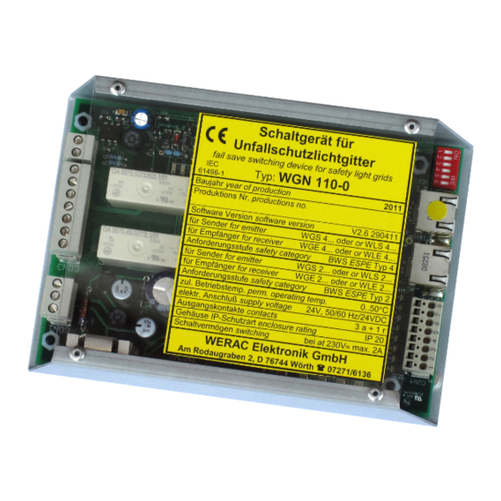
Page 23: Dimensional Drawings
Version 10.12.2019 Dimensional drawings Aufschnappteil für TS 35 grün gelb rot Typenschild Fig. 14: Control unit WGN 100-2 Aufschnappteil für TS 35 grün gelb rot Typenschild Fig.15: Control unit WGN 110-0 WERAC Elektronik GmbH page 23... - Page 24 Fig. 16: Retainer block WHK1 Left Fig. 17: Angle bracket WHW1 for fixing the retainer block Right Fig. 18: Mounting bracket WHW2 for fixing the head pieces 12,2 17,5 Fig. 19: Hinge bracket WSH1 WERAC Elektronik GmbH page 24...
- Page 25 Fig. 20: Emitter, 30 mm resolution with 2 lenses per 50 mm module. The 14 mm resolution has 5 lenses per 50 mm module. Resolution 40 mm has one lense per 35 mm module. WERAC Elektronik GmbH page 25...
Need help?
Do you have a question about the SAFETY 40 and is the answer not in the manual?
Questions and answers