Table of Contents
Advertisement
Quick Links
Advertisement
Table of Contents

Subscribe to Our Youtube Channel
Related Manuals for Supermicro CSE-515B


Summary of Contents for Supermicro CSE-515B
- Page 1 CSE-515B USER’S MANUAL Revision 1.0...
- Page 2 State of California, USA. The State of California, County of Santa Clara shall be the exclusive venue for the resolution of any such disputes. Supermicro's total liability for all claims will not exceed the price paid for the hardware product.
- Page 3 Installation and maintenance should be performed by experienced technicians only. This document lists compatible parts available when this document was published. Refer to the Supermicro web site for updates on supported parts and configurations.
-
Page 4: Table Of Contents
Supermicro CSE-515B Chassis Series User's Manual Contents Contacting Supermicro ......................6 Chapter 1 Introduction 1-1 Overview ..........................7 1.2 Unpacking the Chassis ......................7 1.3 Chassis Features .........................8 Front Features ........................8 1.4 Where to Get Replacement Components ................9 1.5 Returning Merchandise for Service ..................9 Chapter 2 Rack Installation 2.1 Preparing for Setup ......................10... - Page 5 Preface PCI Expansion Cards .......................24 Power Supply ........................27 Appendix A Standardized Warning Statements for DC Systems DC Power Disconnection ....................46 Hazardous Voltage or Energy Present on DC Power Terminals ........48...
-
Page 6: Contacting Supermicro
Supermicro CSE-515B Chassis Series User's Manual Contacting Supermicro Headquarters Address: Super Micro Computer, Inc. 980 Rock Ave. San Jose, CA 95131 U.S.A. Tel: +1 (408) 503-8000 Fax: +1 (408) 503-8008 Email: marketing@supermicro.com (General Information) support@supermicro.com (Technical Support) Website: www.supermicro.com Europe Address: Super Micro Computer B.V. -
Page 7: Chapter 1 Introduction
Chapter 1 Introduction 1-1 Overview Supermicro's CSE-515B chassis is a 1U, short-depth chassis with front I/O ports and redundant power supplies. It can accommodate WIO and Supermicro proprietary motherboards and can support two 2.5" internal storage drives. 1.2 Unpacking the Chassis Inspect the box the chassis was shipped and note if it was damaged in any way. -
Page 8: Chassis Features
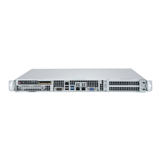
Supermicro CSE-515B Chassis User's Manual 1.3 Chassis Features Front Features The illustration below shows the features on the front of the chassis. Figure 1-1. Front Chassis Features Front Chassis Features Item Feature Description Power Supplies 1 + 1 redundant power supplies... -
Page 9: Where To Get Replacement Components
(http://www.supermicro.com/ support/rma/). Whenever possible, repack the chassis in the original Supermicro carton, using the original packaging material. If these are no longer available, be sure to pack the chassis securely, using packaging material to surround the chassis so that it does not shift within the carton and become damaged during shipping. -
Page 10: Chapter 2 Rack Installation
Supermicro CSE-515B Chassis User's Manual Chapter 2 Rack Installation This chapter provides advice and instructions for mounting your system in a rack. 2.1 Preparing for Setup The box in which the system was shipped should include the hardware needed to install it into the rack. -
Page 11: Precautions
Chapter 2 Rack Installation Precautions • Review the electrical and general safety precautions in the appendix, "Standardized Safety Warnings" in this manual. • Determine the placement of each component in the rack before you install the rails. • Install the heaviest server components at the bottom of the rack first and then work your way up. -
Page 12: Reliable Ground
Supermicro CSE-515B Chassis User's Manual Reliable Ground A reliable ground must be maintained at all times. To ensure this, the rack itself should be grounded. Particular attention should be given to power supply connections other than the direct connections to the branch circuit (i.e. the use of power strips, etc.). -
Page 13: Installing The Rails
Chapter 2 Rack Installation 2.2 Installing the Rails There are a variety of rack units on the market, which may require a slightly different assembly procedure. The following is a basic guideline for installing the system into a rack with the rack mounting hardware provided. - Page 14 Supermicro CSE-515B Chassis User's Manual Figure 2-2. Inner Rails Attached Note: Both front chassis rails and the rack rails have a locking tab, which serves two functions. First, it locks the server into place when installed and pushed fully into the rack (its normal operating position.
-
Page 15: Outer Rack Rails
Chapter 2 Rack Installation Outer Rack Rails Outer rails (p/n MCP-290-00102-0N) attach to the server rack and hold the server in place. These quick-release type outer rails extend to between 25.6 and 33 inches. Installing the Outer Rails to the Rack 1. -
Page 16: Installing The Chassis Into A Rack
Supermicro CSE-515B Chassis User's Manual Installing the Chassis into a Rack Once rails are attached to the chassis and the rack, the chassis is ready to be installed into a rack. Installing the Chassis into a Rack 1. Confirm that inner and outer rails have been properly installed. -
Page 17: Installing The Chassis Into A Telco Rack
Chapter 2 Rack Installation Installing the Chassis into a Telco Rack Follow the procedure below to install the chassis into a Telco (open type) rack. Installing the Chassis into a Telco Rack 1. Use the two L-shaped brackets (four total) to suspend the sides of the chassis within the rack. -
Page 18: Chapter 3 Maintenance And Component Installation
Supermicro CSE-515B Chassis User's Manual Chapter 3 Maintenance and Component Installation This chapter provides instructions on installing and replacing main system components. To prevent compatibility issues, only use components that match the specifications and/or part numbers given. Installation or replacement of most components require that power first be removed from the system. -
Page 19: Accessing The Chassis
Chapter 3: Maintenance and Component Installation 3.2 Accessing the Chassis The chassis top is removable to allow access to components. Removing the Top Cover 1. Remove the screws that secure the cover to the chassis. 2. Slide the cover back and off as directed by the arrow. Caution: Except for short periods of time, do not operate the server without the cover in place. -
Page 20: Chassis Components
3.3 Chassis Components Storage Drives The CSE-515B chassis supports two internal 2.5" storage drives in drive carriers to simplify their removal from the chassis. These carriers also help promote proper airflow. Note: Enterprise level hard disk drives are recommended for use in Supermicro chassis and servers. - Page 21 Chapter 3: Maintenance and Component Installation 4. Secure the drive bracket to the chassis floor using four screws, as shown below. 5. Connect the drive cables to the motherboard and the power supply. 6. If necessary, reinstall the PCI expansion card. 7.
-
Page 22: System Fans
Supermicro CSE-515B Chassis User's Manual System Fans The CSE-515B comes standard with four 40-mm counter-rotating fans. Two additional fans may be added as an option. The fans can adjust their speed according to the heat level sensed in the system, which results in more efficient and quieter operation. -
Page 23: Installing The Motherboard
Permanent and Optional Standoffs Standoffs prevent short circuits by creating space between the motherboard and the chassis surface. The CSE-515B chassis packaging includes optional standoffs (hexagon shaped posts). These standoffs accept the rounded Phillips head screws included in the packaging. -
Page 24: Pci Expansion Cards
Supermicro CSE-515B Chassis User's Manual Figure 3-5. Installing the Motherboard PCI Expansion Cards The CSE-515B has three PCIe expansion slots to support two full-height full-length and one low-profile expansion cards. Note: Install the expansion card after installing the motherboard. Assemble the PCIe Expansion Card, Riser Card, and Brackets 1. - Page 25 Chapter 3: Maintenance and Component Installation Figure 3-7. Expansion Card Assembly 2. Remove the expansion card assembly from the chassis and then remove the PCI slot shield (the L-shaped bracket) from the assembly that is associated with the slot on the chassis you wish to populate, as shown above.
- Page 26 Supermicro CSE-515B Chassis User's Manual Figure 3-8. Installing the Riser Card into the Bracket Figure 3-9. Installing the Riser Card Assembly to the Motherboard...
-
Page 27: Power Supply
Chapter 3: Maintenance and Component Installation Power Supply The CSE-515B supports dual DC power supplies that supply power redundancy. These are Power Management Bus (PMBUS) power supplies to allow for software management. New units can be ordered directly from Supermicro or authorized distributors. -
Page 28: Appendix A Standardized Warning Statements For Dc Systems
Supermicro's Technical Support department for assistance. Only certified technicians should attempt to install or configure components. Read this appendix in its entirety before installing or configuring components in the Supermicro chassis. These warnings may also be found on our website at http://www.supermicro.com/about/... - Page 29 Appendix A: Standardized Warning Statements Warnung WICHTIGE SICHERHEITSHINWEISE Dieses Warnsymbol bedeutet Gefahr. Sie befinden sich in einer Situation, die zu Verletzungen führen kann. Machen Sie sich vor der Arbeit mit Geräten mit den Gefahren elektrischer Schaltungen und den üblichen Verfahren zur Vorbeugung vor Unfällen vertraut. Suchen Sie mit der am Ende jeder Warnung angegebenen Anweisungsnummer nach der jeweiligen Übersetzung in den übersetzten Sicherheitshinweisen, die zusammen mit diesem Gerät ausgeliefert wurden.
- Page 30 Supermicro CSE-515B Chassis Series User's Manual . ٌ ا ك ً ف حالة و ٌ يك أى تتسبب ف اصابة جسذ ة ٌ هذا الزهز ع ٌ خطز !تحذ ز قبل أى تعول عىل أي هعذات،يك عىل علن بالوخاطز ال ا ٌجوة عي الذوائز...
- Page 31 Appendix A: Standardized Warning Statements Warnung Vor dem Anschließen des Systems an die Stromquelle die Installationsanweisungen lesen. ¡Advertencia! Lea las instrucciones de instalación antes de conectar el sistema a la red de alimentación. Attention Avant de brancher le système sur la source d'alimentation, consulter les directives d'installation. .יש...
- Page 32 Supermicro CSE-515B Chassis Series User's Manual Warnung Dieses Produkt ist darauf angewiesen, dass im Gebäude ein Kurzschluss- bzw. Überstromschutz installiert ist. Stellen Sie sicher, dass der Nennwert der Schutzvorrichtung nicht mehr als: 60VDC, 20A beträgt. ¡Advertencia! Este equipo utiliza el sistema de protección contra cortocircuitos (o sobrecorrientes) del edificio.
- Page 33 Appendix A: Standardized Warning Statements Power Disconnection Warning Warning! The system must be disconnected from all sources of power and the power cord removed from the power supply module(s) before accessing the chassis interior to install or remove system components. 電源切断の警告...
- Page 34 Supermicro CSE-515B Chassis Series User's Manual אזהרה מפני ניתוק חשמלי !אזהרה יש לנתק את המערכת מכל מקורות החשמל ויש להסיר את כבל החשמלי מהספק .לפני גישה לחלק הפנימי של המארז לצורך התקנת או הסרת רכיבים يجب فصم اننظاو من جميع مصادر انطاقت وإ ز انت سهك انكهرباء من وحدة امداد...
- Page 35 Appendix A: Standardized Warning Statements Attention Il est vivement recommandé de confier l'installation, le remplacement et la maintenance de ces équipements à des personnels qualifiés et expérimentés. !אזהרה .צוות מוסמך בלבד רשאי להתקין, להחליף את הציוד או לתת שירות עבור הציוד واملدربيه...
- Page 36 Supermicro CSE-515B Chassis Series User's Manual Warnung Diese Einheit ist zur Installation in Bereichen mit beschränktem Zutritt vorgesehen. Der Zutritt zu derartigen Bereichen ist nur mit einem Spezialwerkzeug, Schloss und Schlüssel oder einer sonstigen Sicherheitsvorkehrung möglich. ¡Advertencia! Esta unidad ha sido diseñada para instalación en áreas de acceso restringido. Sólo puede obtenerse acceso a una de estas áreas mediante la utilización de una herramienta especial,...
- Page 37 Appendix A: Standardized Warning Statements Battery Handling Warning! There is the danger of explosion if the battery is replaced incorrectly. Replace the battery only with the same or equivalent type recommended by the manufacturer. Dispose of used batteries according to the manufacturer's instructions 電池の取り扱い...
- Page 38 Supermicro CSE-515B Chassis Series User's Manual هناك خطر من انفجار يف حالة اسحبذال البطارية بطريقة غري صحيحة فعليل اسحبذال البطارية فقط بنفس النىع أو ما يعادلها مام أوصث به الرشمة املصنعة جخلص من البطاريات املسحعملة وفقا لحعليامت الرشمة الصانعة 경고! 배터리가...
- Page 39 Appendix A: Standardized Warning Statements ¡Advertencia! Puede que esta unidad tenga más de una conexión para fuentes de alimentación. Para cortar por completo el suministro de energía, deben desconectarse todas las conexiones. Attention Cette unité peut avoir plus d'une connexion d'alimentation. Pour supprimer toute tension et tout courant électrique de l'unité, toutes les connexions d'alimentation doivent être débranchées.
- Page 40 Supermicro CSE-515B Chassis Series User's Manual Backplane Voltage Warning! Hazardous voltage or energy is present on the backplane when the system is operating. Use caution when servicing. バックプレーンの電圧 システムの稼働中は危険な電圧または電力が、 バックプレーン上にかかっています。 修理する際には注意く ださい。 警告 当系统正在进行时,背板上有很危险的电压或能量,进行维修时务必小心。 警告 當系統正在進行時,背板上有危險的電壓或能量,進行維修時務必小心。 Warnung Wenn das System in Betrieb ist, treten auf der Rückwandplatine gefährliche Spannungen oder Energien auf.
- Page 41 Appendix A: Standardized Warning Statements هناك خطز مه التيار الكهزبايئ أوالطاقة املىجىدة عىل اللىحة عندما يكىن النظام يعمل كه حذ ر ا عند خدمة هذا الجهاس 경고! 시스템이 동작 중일 때 후면판 (Backplane)에는 위험한 전압이나 에너지가 발생 합니다. 서비스 작업 시 주의하십시오. Waarschuwing Een gevaarlijke spanning of energie is aanwezig op de backplane wanneer het systeem in gebruik is.
- Page 42 Supermicro CSE-515B Chassis Series User's Manual תיאום חוקי החשמל הארצי !אזהרה .התקנת הציוד חייבת להיות תואמת לחוקי החשמל המקומיים והארציים تركيب املعدات الكهربائية يجب أن ميتثل للقىاويه املحلية والىطىية املتعلقة بالكهرباء 경고! 현 지역 및 국가의 전기 규정에 따라 장비를 설치해야 합니다.
- Page 43 Appendix A: Standardized Warning Statements Attention La mise au rebut ou le recyclage de ce produit sont généralement soumis à des lois et/ou directives de respect de l'environnement. Renseignez-vous auprès de l'organisme compétent. סילוק המוצר !אזהרה .סילוק סופי של מוצר זה חייב להיות בהתאם להנחיות וחוקי המדינה التخلص...
- Page 44 Supermicro CSE-515B Chassis Series User's Manual Warnung Gefährlich Bewegende Teile. Von den bewegenden Lüfterblätter fern halten. Die Lüfter drehen sich u. U. noch, wenn die Lüfterbaugruppe aus dem Chassis genommen wird. Halten Sie Finger, Schraubendreher und andere Gegenstände von den Öffnungen des Lüftergehäuses entfernt.
- Page 45 Appendix A: Standardized Warning Statements DC Power Supply Warning! When stranded wiring is required, use approved wiring terminations, such as closedloop or spade-type with upturned lugs. These terminations should be the appropriate size for the wires and should clamp both the insulation and conductor. 警告...
-
Page 46: Dc Power Disconnection
Supermicro CSE-515B Chassis Series User's Manual وأ ةقلغم ةقلح لثم ،اهيلع ةقفاوملا ءاهنإ كالسألا مادختساو ،لبسلا مهب تعطقت نيذلا كالسألا ابولطم نوكي امدنع بجيو كالسألل بسانملا مجحلا نوكي تاءاهنإلا هذهل يغبنيو .ةبولقم تاورعلا عم عونلا ةيقيقحلا اهئامسأب ءايشألا .لصومو لزعلا نم لك حبك... - Page 47 Appendix A: Standardized Warning Statements Warnung Vor Ausführung der folgenden Vorgänge ist sicherzustellen, daß die Gleichstromschaltung keinen Strom erhält. ¡Advertencia! Antes de proceder con los siguientes pasos, comprobar que la alimentación del circuito de corriente continua (CC) esté cortada (OFF). Attention Avant de pratiquer l'une quelconque des procédures ci-dessous, vérifier que le circuit en courant continu n'est plus sous tension.
-
Page 48: Hazardous Voltage Or Energy Present On Dc Power Terminals
Supermicro CSE-515B Chassis Series User's Manual Hazardous Voltage or Energy Present on DC Power Terminals Warning! Hazardous voltage or energy may be present on DC power terminals. Always replace cover when terminals are not in service. Be sure uninsulated conductors are not accessible when cover is in place. - Page 49 Appendix A: Standardized Warning Statements امدنع امئاد ءاطغ لادبتسا .ةمصاعلا ةقاطلا تاطحم ىلع ةدوجوم نوكت ةقاطلا وأ ةرطخلا دهجلا دق ءاطغلا امدنع اهيلإ لوصولا نكمي ال لوزعم ريغ تالصوملا هيف كش ال امم .ةمدخلا يف تسيل تاطحملا .هناكم يف 주의! DC전원...
Need help?
Do you have a question about the CSE-515B and is the answer not in the manual?
Questions and answers