Table of Contents
Advertisement
Quick Links
HF-LPX70 Series Wi-Fi&BLE User Manual
Overview of Characteristic
Support Wi-Fi IEEE 802.11b/g/n and BLE 5.0 Wireless Standards
Based on RISC SOC, 160MHz CPU, 276KB RAM,2MB Flash
Support UART Data Communication with Wi-Fi or BLE
Support Wi-Fi STA/AP Mode
Support BLE Smart BLE Link Config
Support Wi-Fi AP Smart AP Link and Sniffer Smart Link V8 Config
Support Wireless and Remote Firmware Upgrade Function
Support Software SDK for Develop
Support Different Antenna Option
HF-LPT170:Internal PCB
Single +3.3V Power Supply for HF-LPT170
Size:
HF-LPT170:22mmx15.6mmx8mm,DIP10package
Shanghai High-Flying Electronics Technology Co., Ltd(www.hi-flying.com)
HF-LPT170
Low Power Wi-Fi +BLE Module
User Manual
V1.4
- 1 -
Advertisement
Table of Contents

Related Manuals for HF HF-LP 70 Series

Summary of Contents for HF HF-LP 70 Series
- Page 1 Support Wireless and Remote Firmware Upgrade Function Support Software SDK for Develop Support Different Antenna Option HF-LPT170:Internal PCB Single +3.3V Power Supply for HF-LPT170 Size: HF-LPT170:22mmx15.6mmx8mm,DIP10package - 1 - Shanghai High-Flying Electronics Technology Co., Ltd(www.hi-flying.com)
-
Page 2: Table Of Contents
HF-LPX70 Series Wi-Fi&BLE User Manual TABLE OF CONTENTS LIST OF FIGURES ........................... 3 LIST OF TABLES ............................ 4 HISTORY ..............................5 PRODUCT OVERVIEW ........................ 5 General Description ......................... 5 1.1. Key Application ........................6 1.1.1 Device Paremeters ......................7 1.1.2 Hardware Introduction ...................... -
Page 3: List Of Figures
HF-LPX70 Series Wi-Fi&BLE User Manual LIST OF FIGURES Block Diagram ........................5 Figure 1. HF-LPT170 Appearance ......................7 Figure 2. HF-LPT170 Pins Map ......................8 Figure 3. Figure 4. HF-LPT170 Mechanical Dimension..................11 Figure 5. Suggested Module Placement Region .................12 Figure 6. -
Page 4: List Of Tables
HF-LPX70 Series Wi-Fi&BLE User Manual LIST OF TABLES Table1. HF-LP170 Module Technical Specifications ................7 Table2. HF-LPT170 Pins Definition ..................... 9 Table3. Absolute Maximum Ratings: ....................11 Table4. Evaluation Kit Interface Description ..................14 - 4 - Shanghai High-Flying Electronics Technology Co., Ltd(www.hi-flying.com) -
Page 5: History
HF-LPX70 Series Wi-Fi&BLE User Manual HISTORY Ed.V1.006-09-2020 FirstVersion. Ed.V1.106-10-2020 Updatesomeerror description Ed.V1.207-16-2020 Update 1MB and 2MB softwaredifference. Ed.V1.308-24-2020 Add HF-LPT170, HF-LPB170, HF-LPB175 type. Ed.V1.409-16-2020 Delete 1MB version, and Add HF-LPT270,HF-LPT271 type. - 5 - Shanghai High-Flying Electronics Technology Co., Ltd(www.hi-flying.com) -
Page 6: Product Overview
HF-LPX70 Series Wi-Fi&BLE User Manual 1. PRODUCT OVERVIEW 1.1.1 Key Application Remote equipment monitoring Asset tracking and telemetry Security Industrial sensors and controls Home automation Medical devices 1.1.2 Device Paremeters Table1. HF-LP170Module Technical Specifications... -
Page 7: Hardware Introduction
HF-LPX70 Series Wi-Fi&BLE User Manual -40℃- 125℃ StorageTemp. <85% Humidity Level 3 HF-LPT270: 22.5mm x 13.5mm x 3mm HF-LPT170: 22mmx15.6mmx8mm HF-LPT271: Dimensions and Size 24mmx16mmx 3mm HF-LPB170: 23.1mm x 32.8mm x 3.5mm HF-LPB175: 41.3mm x 24.1mm x 6mm Network Type... -
Page 8: Hf-Lpt170 Pins Definition
HF-LPX70 Series Wi-Fi&BLE User Manual 1.2.1. HF-LPT170Pins Definition Figure 3. HF-LPT170 Pins Map Table2. HF-LPT170 Pins Definition Describtion Net Name Signal Comments Type Ground Power +3.3V Power Power Detailed functions see <Notes> Multi-Function nReload I,PU GPIO3, PWM3 “Low” effective reset input. There is RC... - Page 9 HF-LPX70 Series Wi-Fi&BLE User Manual Describtion Net Name Signal Comments Type GPIO17 UART1_RX DEBUG_UART1_RX 3.3V TTL UART1 Debug Input GPIO11 9 Module Boot Up nReady “0” – Boot-up OK; Indicator “1” – Boot-up Fail; GPIO4, PWM2 Wi-Fi Status nLink “0” – Wi-Fi connect to router “1”...
-
Page 10: Electrical Characteristics
HF-LPX70 Series Wi-Fi&BLE User Manual 1.2.2. Electrical Characteristics Table3. Absolute Maximum Ratings: Parameter Condition Min. Typ. Max. Unit Work temperature range °C Maximum soldering temperature IPC/JEDEC J-STD-020 °C ESD (Human Body ModelHBM) TAMB=25°C ESD (MM) TAMB=25°C 0.25 - 10 -... -
Page 11: Hf-Lpt170Mechanical Size
Figure 4. HF-LPT170 Mechanical Dimension 1.2.4. PCB Antenna HF modules support internal PCB antenna option. When customer select internal antenna, you shall comply with following antenna design rules and module location suggestions: For customer PCB, module antenna area can’t put componet or paste GND net;(See the following red arrow area) ... -
Page 12: Evaluation Kit
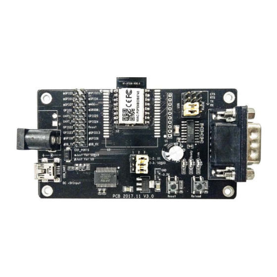
HF-LPX70 Series Wi-Fi&BLE User Manual Figure 5. Suggested Module Placement Region 1.2.5. Evaluation Kit High-Flying provides the EVK to promote user to familiar the product and develop the detailed application. The evaluation kit shown as below, user can connect to module with the RS-232 UART, USB (Internal USB to UARTconvetor) or Wireless interface to configure the parameters, manage the module or do the some functional tests. -
Page 13: Order Information
LED Link nLink LED Smartlinkand Restore factory default configuration. Button nRelo SeemoreforPINDefinition 1.2.6. Order Information Base on customer detailed requirement, HF-LP170 modules provide different variants and physical type for detailed application. - 13- Shanghai High-Flying Electronics Technology Co., Ltd(www.hi-flying.com) -
Page 14: Hardware Typical Application
HF-LPX70 Series Wi-Fi&BLE User Manual Figure 8. HF-LPT170 Order Information 1.2.7. Hardware Typical Application Figure 9. HF-LPT170 Hardware Typical Application Notes: nReset- Module hardware reset signal. Input. Logics “0” effective. There is pull-up resister internal and no external pull-up required. When module power up or some issue happened, MCU need assert nRST signal “0”... - Page 15 HF-LPX70 Series Wi-Fi&BLE User Manual (This pin is recommend to connect to LED, indicate status when the module in wireless upgrade mode) When module connects to AP (AP associated), this pin will output “0”. This signal used to judge if module already at WiFi connection status.
-
Page 16: Appendix D:contact Information
HF-LPX70 Series Wi-Fi&BLE User Manual APPENDIX D:CONTACT INFORMATION ------------------------------------------------------------------------------------------------------------ Address:Room 1002,Building 1,No.3000,Longdong Avenue,Pudong New Area,Shanghai,China,201203 Web:www.hi-flying.com Service Online:400-189-3108/18616078755 Sales Contact: sales@hi-flying.com ----------------------------------------------------------------------------------------------------------- For more information about High-Flying modules, applications, and solutions, please visit our web site http://www.hi-flying.com/en/ © Copyright High-Flying, May, 2011 The information disclosed herein is proprietary to High-Flying and is not to be used by or disclosed to unauthorized persons without the written consent of High-Flying. -
Page 17: Oem/Integrators Installation Manual
This module can be used in IoT devices. The input voltage to the module should be nominally 3.3VDC and the ambient temperature of the module should not exceed 85℃. HF-LPT170 has one PCB antenna with max antenna gain 2.0dBi. If the antenna needs to be changed, the certification should be re-applied. - Page 18 9. Additional testing, Part 15 Subpart B disclaimer The final host / module combination need to be evaluated against the FCC Part 15B criteria for unintentional radiators in order to be properly authorized for operation as a Part 15 digital device. The host integrator installing this module into their product must ensure that the final composite product complies with the FCC requirements by a technical assessment or evaluation to the FCC rules, including the transmitter operation and should refer to guidance in KDB 996369.
Need help?
Do you have a question about the HF-LP 70 Series and is the answer not in the manual?
Questions and answers