Table of Contents
Advertisement
Quick Links
Advertisement
Table of Contents
Troubleshooting

Summary of Contents for SAMES KREMLIN Magna-Ram
- Page 1 Magna-Ram 300 Gallon Elevator and Controls...
- Page 2 All communication or reproduction of this document, in any form whatsoever and all use or communication of its contents is forbidden without express written authorization from SAMES KREMLIN, Inc. The descriptions and characteristics mentioned in this document are subject to change without prior notice.
-
Page 3: Table Of Contents
1.10.3 Commercial Products ......................10 1.11 General Electrostatic Systems ...................... 11 1.11.1 Manual Electrostatic Systems ....................12 2 Magna-Ram ............................13 2.1 Complete Magna-Ram with double ball pumps................14 2.1.1 Double Ball Pumps ........................ 15 3 Specifications ............................16 3.1 ... - Page 4 7 The Magna-Ram consists of seven major components............... 28 7.1 The Pumps Packages........................29 7.2 Magna-Ram Elevator (Ram). 62-3147-01 (RH) / 62-3147-02 (LH) ..........29 7.2.1 Elevator 62-3147-0x components..................30 7.2.2 Upper Frame and follower Assembly..................31 ...
- Page 5 7.13.2 Powered Vents 668-160-205 (Standard) ................59 7.13.3 Gravity Vents 668-160-206 (Optional) ................... 60 7.14 Outlet Porting ..........................61 7.14.1 62-3220-01 Material Outlet-Steel..................62 7.14.2 62-3220-02 Material Outlet-Steel..................63 7.14.3 62-3220-03 Material Outlet-Plated..................64 7.14.4 62-3220-04 Material Outlet-Plated..................65 7.15 ...
-
Page 6: Safety
Safety Introduction SAMES KREMLIN, Inc. is not and does not represent itself as an expert in safety systems, safety equipment, or the specific safety aspects of your company and/or its work force. It is the responsibility of the owner, employer, or user to take all necessary steps to guarantee the safety of all personnel in the workplace. -
Page 7: General Safety Instructions
General Safety Instructions Only trained and certified personnel should attempt to operate any equipment. (To acquire necessary training, please contact the training center in Plymouth Michigan at 734-979-0100). Supervisors must ensure that personnel are properly trained in the safe usage of all equipment as well as proper procedures which are outlined in system manuals for parts and accessories. -
Page 8: Pressure Hazards
Pressure Hazards Current legislation requires that an air relief shut off valve is mounted on the supply circuit of the pump motor as to bleed residual air pressure when closing the circuitry. Without this precaution, the motors residual air pressure may allow the pump to generate excessive pressure which may result in injury. -
Page 9: Toxic Product Hazards
Toxic Product Hazards Toxic materials and vapors can cause severe injury not only though contact with the body, but also if they are ingested or inhaled. Therefore, it is imperative that personnel; Know the material products and risks they are being exposed to. Properly read all •... -
Page 10: Equipment Requirements
Negative reactions (from non-compatible materials) can cause very serious conditions to the user. Therefore, SAMES KREMLIN, Inc. assumes no liability for: Any user equipment not designed to be compatible with a specific chemical •... -
Page 11: General Electrostatic Systems
1.11 General Electrostatic Systems The introduction of high voltage electricity into a highly volatile and explosive atmosphere requires that the following additional design practices be observed for electrostatic spray operations: 1. Transformers, power packs, control apparatus, and all other electrical portions of the equipment, (except for high voltage grids and cascades and electrostatic atomizing heads and their connections) should be located outside the spraying area, unless otherwise specified. -
Page 12: Manual Electrostatic Systems
10. Employees should not work on electrostatic equipment while the voltage is applied. Fail-safe photoelectric or body-capacitance safety controls or their equivalent safeguards should be installed as to ensure the power supply will shut down should a person approach the equipment while in operation. -
Page 13: Magna-Ram
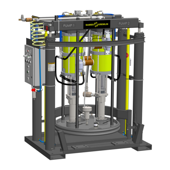
Overview Magna-Ram The Magna-Ram is a single component bulk supply delivery system. It can transfer viscous sealants and adhesives from a 300-gallon MagnaDrum container. The Magna-Ram a features dual pump design that provides high material volumes and pressure. The Magna-Ram can be centrally located to supply multiple applications. -
Page 14: Complete Magna-Ram With Double Ball Pumps
Key | Control Panel location RH= Right Side | LH= Left Side | All dual Magna-Rams included a RH & LH elevator The Magna-Ram assemblies can be ordered with control panels on the right- or left-hand side of the elevator. An automatic crossover system will supply both a right and left elevator assembly... -
Page 15: Double Ball Pumps
2.1.1 Double Ball Pumps REXSON has developed standard Double Ball pump offerings. A wide range of ratio and volume are available. Ratios (4:1 – 80:1), Volume (79cc – 1000cc) Note: All specifications are per single pump. *Other selections are available - More details are in the Master Pump Catalog. -
Page 16: Specifications
Specifications Specifications Specifications Benefits Ram Width / Depth 86.7 in. (220.cm) Wide – 50.1 in. (127cm) Deep Ram Down Height 87 in. (221cm) Ram Up Height 144in. (366cm) Elevated Drum Load 5.9in. (15cm) Height Pump Working air Psi Minimum 45 Psi (3.1 bar) / Maximum 87 Psi (6 bar) Air SCFM Pumps 100 to 200 SCFM (340 m /h) - (See Pump Information for actual requirements) -
Page 17: Ram Retracted
Ram Retracted. Ram Extended. Version B June, 2020 MagnaRam-SK... -
Page 18: Load Height
Load Height Version B June, 2020 MagnaRam-SK... -
Page 19: Installation
Installation Installation Installation Instructions: Locate MagnaRam. a. Place MagnaRam in desired location and anchor to the floor. b. Verify that raised height clearance is at least 150+inches (381cm). c. Leave enough room to walk around- Minimum of 3ft (1meter). i. The front must be clear for loading. d. -
Page 20: Install Air Supply Hose
Install Air Supply Hose. 1. Close all ball valves on the upper frame: a. P1- Main air supply Primary b. P2- Control air supply c. P3 - Pump #1 air supply. d. P4 - Pump #2 air supply. e. P5 – Depressurization valve (Option). H1 –... -
Page 21: Install Material Hose
Install Material Hose. 1. Install the Material supply hoses to Material Outlet port. a. Verify that the outlet hose is within the pressure rating of the pump. b. Outlet Port is #24JICM c. Run the elevator up and down. i. Verify that there are no clearance issues. ii. -
Page 22: Pneumatic Single Pneumatics
Pneumatic Single Pneumatics. 1. The MagnaRam may require single or dual pneumatic configuration. a. The Magna-Rams can be easily changed from single to dual crossover pneumatics. b. Single/Dual pneumatics allow the MagnaRam to start/stop the pumps. Dual system – Closes the depressurization valves, even if the pumps are started on the remote pump. -
Page 23: Dual Magna-Ram - With Automatic Crossover
Dual Magna-Ram – With Automatic Crossover. a. Remove plug from tube 21A. b. Install interconnect tube from Magna-Ram “A” port 21 to Magna-Ram “B” port 34. c. Install interconnect tube from Magna-Ram “B” port 21 to Magna-Ram “A” port 34. -
Page 24: Preventative Maintenance
Preventative Maintenance Preventative Maintenance MagnaRam Maintenance Schedule Time Description Resolve Period Assure that both pumps are function correctly. Check Bleed air from pump/ rebuild if for leaks and single stroking. necessary Daily Verify that the pumps air pressure is within range. Adjust air regulator if required Verify that the Elevator Up/Down pressure is within Adjust air regulator if required... -
Page 25: Operation
Operation Operation: See Control Box 65-3290-00 Operation section for description and functions of the control panel. Unloading Material. Step 1 Step 2 1. Turn the Pump Off by either. a. Depressing the Pump Off Button b. Depressing the Depressurization 1. Verify that the Drum Clamps (2) are Button. -
Page 26: Loading Material
Loading Material. Step 1 Step 2 1. Verify that both Barrel Clamps are in the 1. Close the Drum Clamps (2). up position. 2. Before Lowering the follower plate, ensure 2. Lubricate the Follower Plate Seals with a that there is nothing between the Follower, compatible lubricant. -
Page 27: Magnaram Drum Safety Concerns
6.2.1 MagnaRam Drum Safety Concerns. 1. If a system has Automatic crossover the pumps may start at any time. a. Use the pump lock-out valves to prevent the pumps from starting while preforming maintenance. 2. Always use the drum clamps when the pump is in operation. They secure the drum and prevent lifting when the ram is in the up direction. -
Page 28: The Magna-Ram Consists Of Seven Major Components
2. Elevator – Raises and Lowers the Follower Plate/Pumps in the Drum 3. Control Panel – User interface to operate, control and monitor the Magna-Ram. 4. Upper Frame – Connect the elevator to Follower Plate and contains control valve for pumps. -
Page 29: The Pumps Packages
The Pumps Packages. Many different pumps can be used with The Magna-Ram. The pumps may be Double Ball or Shovel Check. Many ratio and volume sizes are available. Reference 2.1.1 2.1.2 They range from: Ratio (18:1 – 60:1) or Volume (340cc -1000cc) Pump 1 is always on the left and Pump 2 is always on the right. -
Page 30: Elevator 62-3147-0X Components
7.2.1 Elevator 62-3147-0x components. The Elevator raises and lower the pumps. It uses four 5.5inch (13.97cm) piston assemblies to create the force required to lift and apply down force priming the fluid sections. Torque to: 190 Lb-Ft (258 Nm) Torque to: 65 Lb-Ft (88 Nm) All bolts and fittings are to be Torque to: 30... -
Page 31: Upper Frame And Follower Assembly
7.2.2 Upper Frame and follower Assembly. Located on back Side of Elevator Item Qty. Part No. Description Item Qty. Part No. Description 62-3241-01 Follower Plate Assy 65-3056-01 Header, Material Outlet 62-3242-01 Power Vent Assy (2 vents) 62-3263-01 Drum Level Limit Switch 65-3225-01 Upper Frame Pneumatics 72-3041-07... -
Page 32: Elevator Guide Bushing Assembly 62-3009-03
Torque to: 65 Lb-Ft (88 Nm) Item Qty. Part No. Description Item Qty. Part No. Description 72-2999-01 Guide Bushing,Magna-Ram 350-141 Bleeder Valve, 1/8NPTM 2∆ 82-3883-04 O-Ring, Buna 1 ½ x 1 7/8 in 5∆ 82-3883-05 Rod Scraper 1 ½ x 2 in. 3∆... -
Page 33: Elevator Piston Assembly 62-3009-02
O-Ring, Buna 5 x 5 ½ in. 82-5298-05 SHCS M24-3 x 80mm 82-0720-44 O-Ring Viton 1 ½ x 1 11/16” 72-2998-04 Piston Rod MagnaRam 72-2998-02 Piston, Magna-Ram MagnaRam. Cylinder MagnaRam, Cylinder Repair Kit (Guide Bushing Repair kit (Guide 62-3393-01 62-3393-04 and Piston kit for 1 Bushing and Piston kit cylinder). -
Page 34: Removing/ Installing The Elevator Piston Assembly
7.2.5 Removing/ Installing the Elevator Piston Assembly. Removal: 1. Support the Follower and Ram assembly on a crate see example. 2. Remove the M24 Hex nut (24,25) and Lock washer from the frame. 3. Lower the Elevator Rods. Depressurize the elevator air pressure. -
Page 35: Elevator Control Tubing 65-3224-01
7.2.6 Elevator Control Tubing 65-3224-01 Right Hand elevator 1/2in. Red = Elevator Down Blue = Elevator Up Magenta = Control air down Aqua = Control air up. Apply Loctite 567 to all Hose shown in different colors – Actual hose color is blue. pipe threads. -
Page 36: Barrel Clamps 62-3035-00
Barrel Clamps 62-3035-00 Used to prevent the drum from moving up when the follower plate is being removed from the drum. ASSEMBLY 1. Bolt Side Plates (1) to MagnaRam base using (7,8,14) 2. Install the Clamp Stop (11,12,13) in the Side Plates (1). Do Not Overtighten. -
Page 37: Safety Ram Up Lockout 62-3065-01
Safety Ram Up Lockout 62-3065-01 This Lockout is used to prevent the ram from falling. When the ram is fully extended a pin can be inserted through the tube and a Safety Lock can be installed. There are two Ram Up bars, and each requires a separate Lock. -
Page 38: Operation And Lock-Out Sticker And Tags
Operation and Lock-out Sticker and tags. Replacement Stickers/Tags Item Qty. Part No. Description 72-3091-00 Label, SAMES-KREMLIN, 5in. x 18in (Green Text/Black) 72-3361-01 Tags, Lamacoid, MagnaRam Pump Numbers 72-3361-02 Label, MagnaRam Lockout/Tagout Information 72-3361-03 Label, MagnaRam Hazard Warning 72-3361-04 Labels, Set Lockout/Tagouts Version B June, 2020 MagnaRam-SK... -
Page 39: Control Box Components
Control Box Components Empty Drum Indicator (13) Pumps On (21) Pump #1 Pressure (9) Pump #2 Pressure Pump #1 Air Regulator (8) Pump #2 Air Regulator (8) Pump On Pushbutton (11) Pump Off Pushbutton (11) Depressurize Pushbutton (11) Power Vents On/Off Selector Switch (12) Door Locks Ram Raise Pushbutton (11) -
Page 40: Control Box Inside Components
7.6.1 Control Box Inside components. Pump #1 Start/Stop (7) Pump #2 Start/Stop (7) Crossover- Pump Start Depressurize Off SV One Shot Valve (15) (14) Pump Control Valve VLV Gauge 1/8NPT 0-160 (20) Pump Stop SV2 (14) Pump Start SV (14) Raise/Lower Power Regulator/Valve Depressurize Control... -
Page 41: Control Box Top
7.6.2 Control Box Top Tube numbers and component descriptions are shown below. If using a single stand-alone panel Plug – Pump Start Crossover-Out #21 and Depressurize Stop to Remote #4. Version B June, 2020 MagnaRam-SK... -
Page 42: Control Box 65-3290-00 Operation
7.6.3 Control Box 65-3290-00 Operation Basic Magna-Ram Pneumatic control box with automatic crossover option. The Control Box main functions are: 1. Stops / Raises / Lowers the Elevator. a. In stop position both up and down air is blocked- no movement. -
Page 43: Control Box Door Layout
7.6.4 Control Box Door Layout Version B June, 2020 MagnaRam-SK... -
Page 44: Control Box Subplate Layout
7.6.5 Control Box Subplate Layout Version B June, 2020 MagnaRam-SK... -
Page 45: Control Box Back Layout
7.6.6 Control Box Back Layout Version B June, 2020 MagnaRam-SK... -
Page 46: Control Box Part Numbers
7.6.7 Control Box Part Numbers Item Qty. Part Number Description 82-5617-01 ENCLOSURE, 24H X 16WX 8D 82-5617-02 SUBPLATE, 21H X 13W 72-3291-00 TAGS, SET, PNEUMATIC PANEL, MAGNARAM 72-3386-00 NAMEPLATE, MAGNARAM PANEL 65-3435-00 VALVE 3-POS. 4-WAY, PILOT OP. DUAL PRESS. W/ REG 85-5616-10 VALVE, 2 POS. -
Page 47: Empty Drum Switch 62-3263-01
Empty Drum Switch 62-3263-01 Sends single to control panel to turn off the pumps and automatic crossover to start opposing pumps. ADJUSTMENT 1. Move the elevator to the Down/Empty height. 2. Loosen Screws (7) to move the valve closer of further from the frame. -
Page 48: Control Box/Lock-Out Bracket 62-3228-01
Control Box/Lock-Out Bracket 62-3228-01 The Brackets are used to Hold the Control Box and provide stability for the Follower Lock-Up safety bars. Shown 90º rotated Control Box Mounting Bolts Bracket Mounting position. 22.6 in (575mm) 39.4 in (1000mm) Item Qty. Part No. -
Page 49: Upper Frame Pneumatic Assembly 65-3225-01
Upper Frame Pneumatic Assembly 65-3225-01 The Pneumatic Assembly is bolted to the Upper Frame. Pilot regulators are 1:1 ratio Maximum Psi 87 Psi (6 bar) Apply Loctite 567 to all pipe threads. Item Qty. Part No. Description Item Qty. Part No. Description 82-1100-20 Elbow, 3/8NPTx3/8Tube... -
Page 50: Upper Frame Pneumatic Connections
7.9.1 Upper Frame Pneumatic Connections Plant Air Supply 1 in. #16JICM Clean Dry Free of Oil and Liquids 5 Micron Filter Max 87 Psi (6 bar) Depressurization Valve Air Supply Air Motor Control Air Supply 1 & 2 (option) Control Panel Air Supply Pump #1 Pump #1... -
Page 51: Pneumatics Shown Assembled To Upper Frame
7.9.3 Pneumatics Shown assembled to upper frame. Depressurization Air Supply Plant Air Supply to Air Motor MagnaRam Control Air supply Regulated Air to Pumps Mounting Clamps Controls Air supply Version B June, 2020 MagnaRam-SK... -
Page 52: Pump Air Supply Kit 65-3223-01
7.10 Pump Air Supply Kit 65-3223-01. Used on single air cylinder configurations. To Upper Frame Pump Air Outlet Connections Reference Pumps Remove Muffler: Add 90º fittings to Angle shown Replace Muffler. Apply Loctite 567 to all pipe threads. Q2ty Item Qty. -
Page 53: Pump Air Supply Kit 65-3223-02
7.11 Pump Air Supply Kit 65-3223-02. Used on dual air cylinder configurations. To Upper Frame Pump Air Outlet Connections Remove Muffler: Add 90º fitting and Nipple, face Muffler in Up direction - All 4 Valves Hoses to Upper Valve Hoses to Lower Valve Back of MagnaRam... -
Page 54: Utility Routing Assembly
7.12 Utility Routing Assembly. Item Qty. Part No. Description Item Qty. Part No. Description 72-3272-05 Bracket, Pilot Supply Assy. 82-3321-00 SHCS ¼-20 x ½” 72-3272-03 Clamp, Coil Tubing 350-118 SHCS ¼-20 x 1-1/4”” 72-3098-02 U-Bolt, Sq. 3in. 3/8-16 Thd. 82-3384-19 Bulkhead Fitting, ½”NPTF 85-5595-07 Tubing Coil, 3 Tube ¼... -
Page 55: Pilot Supply Bracket Layout
7.12.1 Pilot Supply Bracket layout. Connect tubing coils to Bracket and top of control panel. See Schematic. Color Code of Tubing Coil #4 7.12.2 Utility Routing Assembly Installed. 1. Bracket, Pilot supply 2. Tubing Coils, Signals a. See wiring schematic for tubing connections 3. -
Page 56: Utility Brackets Tube Connections
7.12.3 Utility Brackets Tube Connections Tubing Coil Color Pilot Supply Bracket Tubing Tubing Coil #1 Coil #2 Version B June, 2020 MagnaRam-SK... -
Page 57: Magna-Ram Follower Plate. 62-3241-01
7.13 Magna-Ram Follower Plate. 62-3241-01 The follower plate is designed to seal the MagraDrum inner diameter 42.500 + 0.010 inches that has a 32µ finish. The seam weld must be radiused to match the drum. The Follower plate is made of steel that is powder coated black. -
Page 58: Follower Plate Assembly 62-3241-01
7.13.1 Follower Plate Assembly 62-3241-01. Bleeder valves and 1/2NPT pipe plug can be switched to change the direction of bleeding air from the follower. Item Qty. Part No. Description Item Qty. Part No. Description 72-3240-00 Follower, 300 Gallon-bare 85-5616-09 Plug, 1/2NPT 401-101 Bleeder Valve, 1/2NPT 82-3162-00... -
Page 59: Powered Vents 668-160-205 (Standard)
7.13.2 Powered Vents 668-160-205 (Standard) Air cylinder force ensures a leak free valve. Tapered Valve design prevents leaks and lasts. Positive opening/closing using air cylinder. Open Close Vent Valve shown closed Tapered Valve Follower Plate Lockout and Depressurize air supply before removing valve. Removal. -
Page 60: Gravity Vents 668-160-206 (Optional)
7.13.3 Gravity Vents 668-160-206 (Optional) Uses Gravity (valve weight) to open and close. When material pushes on plunger. The valve closes and uses an O-ring to seal. Valve Weight O-ring Plunger Follower Plate Removal. 1. Hold the Weight #1 and using a socket remove the 3/8 Nut #9#8. Lubricate #6 O-Ring with 2. -
Page 61: Outlet Porting
7.14 Outlet Porting The Magna-Ram Outlet Porting includes a high-pressure Y-fitting that has (2) 1-1/4NPT inlet ports and a 1-1/2NPT outlet port that includes a #20JICM adaptor. The material hoses from the pump are included in kits designed for different fluid sections. -
Page 62: Material Outlet-Steel
7.14.1 62-3220-01 Material Outlet-Steel. Adaptor 1-1/2”BSPM with Steel - Side Port Check Valve. Use Fittings from Hose Assembly Pumps shown for reference only. Apply Loctite 567 to all pipe threads. Item Qty. Part No. Description Item Qty. Part No. Description Side Port Check Valve 85-5595-13 Elbow, St. -
Page 63: Material Outlet-Steel
7.14.2 62-3220-02 Material Outlet-Steel. Adaptor 1”BSPM with Steel - Side Port Check Valve. Use Fittings from Hose Assembly Pumps shown for reference only. Apply Loctite 567 to all pipe threads. Item Qty. Part No. Description Item Qty. Part No. Description Nipple, 1”BSPTM x 72-2816-02 Bleeder Valve 1/4NPT... -
Page 64: Material Outlet-Plated
7.14.3 62-3220-03 Material Outlet-Plated. Adaptor 1-1/2”BSPM with Plated - Side Port Check Valve. Use Fittings from Hose Assembly Pumps shown for reference only. Apply Loctite 567 to all pipe threads. Item Qty. Part No. Description Item Qty. Part No. Description Hose Rubber, 1/14”x2’... -
Page 65: Material Outlet-Plated
7.14.4 62-3220-04 Material Outlet-Plated. Adaptor 1”BSPM with Plated -Side Port Check Valve. Use Fittings from Hose Assembly Pumps shown for reference only. Apply Loctite 567 to all pipe threads. Item Qty. Part No. Description Item Qty. Part No. Description Nipple, 1”BSPM x 1/4NPT Bleeder Valve 72-2816-02 402-763CP... -
Page 66: Side Port Check Valve 62-3213-01 - 1-1/4Nptf
7.15 Side Port Check Valve 62-3213-01 – 1-1/4NPTF The Side Port Check Valve prevents the back flow of mated from the output header or hose. The valve is required if more than one pumps is connected to the same outlet. The valve allows the pump to be isolated from the outlet supply for bleeding and maintenance purposes. -
Page 67: Side Port Check Valve 62-3213-02 - 1-1/4Npt - Plated
7.16 Side Port Check Valve 62-3213-02 – 1-1/4NPT - Plated The Side Port Check Valve prevents the back flow of mated from the output header or hose. The valve is required if more than one pump is connected to the same outlet. The valve allows the pump to be isolated from the outlet supply for bleeding and maintenance purposes. -
Page 68: Pump Installation Assembly 62-3244-01 (105Mm)
7.17 Pump Installation Assembly 62-3244-01 (105mm). Caution Eye Bolt Only supports Air Motor Fits Pumps: 2B 40.453 2B 40.750 2B 30.980 2B 60.1000 Remove Pump Flange to install Collar #1 Lubricate O-Ring with compatible Grease Item Qty. Part No. Description Item Qty. -
Page 69: Pump Installation Assembly 62-3244-03 (80Mm)
7.18 Pump Installation Assembly 62-3244-03 (80mm). Caution Eye Bolt Only supports Air Motor Fits Pumps: 2B 53-360 Remove Pump Flange to install Collar #1 Lubricate O-Ring with compatible Grease Item Qty. Part No. Description Item Qty. Part No. Description 72-3152-03 Pump Bolt Collar 74mm 360-573 O-Ring,Viton 3-7/8x4-1/4... -
Page 70: Depressurization Kit 65-3056-04
7.19 Depressurization Kit 65-3056-04 The Depressurize kit works with the control panel. When the operator selects depressurize: 1. The Pumps are turned off – Pilot air to regulators is stopped. 2. A pilot signal #19 is sent to the Depressurization signal valve- Shifting the valve. 3. -
Page 71: Depressurization Components
7.19.1 Depressurization Components: Material Inlet Supply Apply Loctite 567 to all pipe threads. Material Outlet Item Qty. Part No. Description Item Qty. Part No. Description 105-034N Depressurization Valve 350-940 Nipple 1/4”NPT x 3in. Fitting 1/4”NPT x 3/8ODT Valve, Pilot 2pos-4way 350-875 361-650 Pushlok... -
Page 72: 105-034N Depressurization Vavle
7.20 105-034N Depressurization Vavle WHEN REPAIRING THE VALVE, TURN OFF THE AIR SUPPLY AND BLEED THE 6.0 in. MATERIAL PRESSURE FROM THE PUMPING SYSTEM. 1/4” NPT Closed SERVICE KITS Use only SAMES-KREMLIN Inc. replacement parts to ensure compatibility and longest life. Depressurize Valve Repair Kit : 105-034NRK SPECIFICATIONS... -
Page 73: 105-034N Depressurization Valve Componants
7.20.1 105-034N Depressurization Valve componants 350-914 SHCS (6) 1/4-20 x .75 361-322 (6) Lock Washer 402-834 End Cap ∆ 361-733 361-736 ∆ (2) O-Ring Spring ∆ 363-224 365-194 ∆ Button Cap Screw Hardened Washer ∆ 361-734 402-835 (2) O-ring Air Piston 402-924 ∆... -
Page 74: Depressurization Valve Dis-Assembly
7.20.2 Depressurization Valve Dis-Assembly 105-034N Shut Off Valve Disassembly: Socket Screw & Lock Washers End Cap WHEN REPAIRING THE VALVE, TURN OFF THE AIR SUPPLY AND BLEED THE MATERIAL PRESSURE FROM THE PUMPING SYSTEM. 361-733 O-Ring Spring Button Screw Removal from Follower Plate. Hardened Washer 361-734 O-Ring 1. -
Page 75: 105-034N Depressurization Valve Assembly
7.20.3 105-034N Depressurization Valve Assembly 105-034N Shut Off Valve Disassembly: Socket Screw & Lock Washers WHEN REPAIRING THE VALVE, TURN OFF THE AIR SUPPLY AND BLEED THE End Cap MATERIAL PRESSURE FROM THE PUMPING SYSTEM. Assembly: 361-733 O-Ring Lubricate all Seals and O-Rings. Spring 1. -
Page 76: Troubleshooting
Troubleshooting Trouble Shooting Trouble Shooting MagnaRam Problem Description Resolve Closed main air or clogged/ plugged air Turn on (open) Main air. supply. Clean/ Replace air supply line. Not enough air Pressure or supply hose Supply pressure too low increase too small. pressure. -
Page 77: Trouble Shooting Air Motor
Trouble Shooting Air Motor Trouble Shooting Air Motor Problem Description Resolve Turn On Pumps and adjust pressure Pumps Not turned On at Control Panel using the regulator. Air supply to upper frame or control box Turn On air supply to upper frame or is off. -
Page 78: Trouble Shooting Magnaram Fluid Section
Trouble Shooting MagnaRam Fluid Section. Trouble Shooting Fluid Section Problem Description Resolve Check Elevator Down Pressure. Air inside. Open bleeder valve on fluid section and cycle pump to remove air. Replace upper ball or Piston (upper) Upper check is not seating Not delivering Material in –... -
Page 79: Recommended Spare Parts
Spare Parts Recommended Spare Parts Magnadrum Recommended Spare Parts Rec. Lead Section Part Number Description Qty. time 62-3393-04 MagnaRam cylinder Repair Kit (4cyl) 350-141 Bleeder Valves Elevator 85-5595-01 Hose, Air 1/2” 300Psi Blue 10ft. 62-3035-00 Barrel Clamp Assembly 72-3064-10 Safety Ram Up Lock-Out Pin 82-3760-40 Control Air Filter 1/2”NPT 85-5618-05... -
Page 80: Control Drawings 45-0538-00
Drawings 10 Control Drawings 45-0538-00 Version B June, 2020 MagnaRam-SK...
Need help?
Do you have a question about the Magna-Ram and is the answer not in the manual?
Questions and answers