Advertisement
Quick Links
Advertisement

Summary of Contents for featuring BS-201
- Page 1 Bluetooth 5.0 to Serial Port Converter BS-201 Operation Manual v.201812a...
-
Page 2: Table Of Contents
Table of Contents 1 Introduction ---------------------------------------------------------------------------------- 2 2 Package checklist-------------------------------------------------------------------------- 3 3 Product Specifications ------------------------------------------------------------------- 4 4 Product Panel Views Description ---------------------------------------------------- 5 5 Hardware Installation --------------------------------------------------------------------- 9 A ------------------------------------------------------------------------------------ 11... -
Page 3: Introduction
1 Introduction Thank you for purchasing of BS-201 Bluetooth 5.0 to Serial Port Converter. Featuring Bluetooth wireless technology, it is used as extensional connection for standard RS-232 or industrial RS-422/485 cable. It can be easily adapted to industrial machines with RS-232 or RS-422/485 interfaces. -
Page 4: Package Checklist
2 Package checklist BS-201 product is shipped with the following items: 1 unit of BS-201 Bluetooth to RS-232/422/485 converter 1 unit of Power Adaptor (9V DC, 200mA) is an option. User Operation Manual Software CD NOTE: Notify your sales representative if any of the above items is missing or damaged... -
Page 5: Product Specifications
3 Product Specifications Features • Support Bluetooth 5.0 • Maximum data throughput 1 Mbps • Maximum packet size 250 bytes • Transmission range up to 100 Meters. • Built in 15KV ESD protection for signals • RS-422/485 surge protection • Windows Configuration Utility Software features System ... -
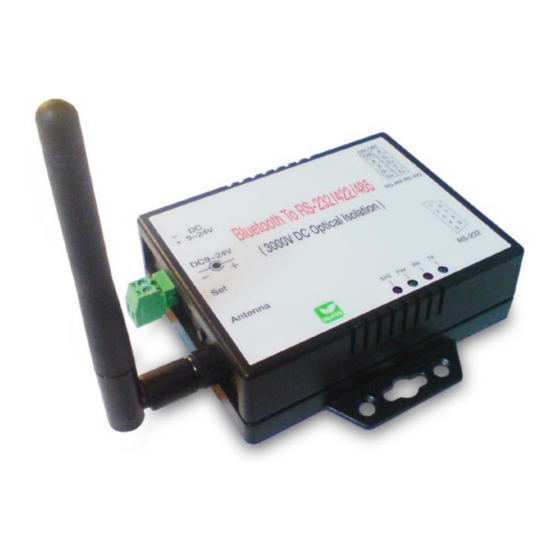
Page 6: Product Panel Views Description
LED Indicators DC-In Power Outlet The BS-201 Bluetooth to RS232 / 422 / 485 is powered by a single 9V DC (Inner positive/outer negative) power supply and 200mA of current. A suitable power supply adapter is part of the package. Connect the power line to the power outlet beside of... - Page 7 Antenna Connector Antenna The antenna is a standard SMA jack. Simply connect it to a 2.0dBi dipole antenna (Standard Rubber Duck) and it is 50 Ohms impedance and can support 2.4GHz frequency. Serial I/O Port Serial I/O Port RS-485/RS-42 Terminal Serial I/O Port Resister RS232...
- Page 8 RS-485/RS-422 I/O. If the switch 1 & 2 are set in “ON” position, the signal compensation will be activated. To disable the function, just to push switch 1 & 2 to opposite position. Reset Button Reset Button This button is for synchronizing BS-201 device with Utility “BT5_Uart_Config” software.
- Page 9 SYS (Green): : : : When LED is constantly ON, device is in normal Transparent mode. When BS-201 is in Master role and not pair with Slave device yet, the LED will be blinking if there is other Slave device not paring with.s When pressing AT Command Key for more than 4 seconds, the LED will be blinking.
-
Page 10: Hardware Installation
5 Hardware Installation 1. Connect host computer with a RS-232 cable to BS-201. A crosslink cable or adaptor for parallel cable is required. Power on the BS-201 with a DC power adapter or 2-wire. The SYS LED will be ON. - Page 11 5. Click the “Connect” button. If the Com Port is correct, the “Connect” button will change to “Disconnect” and the below “Read” / “Write” button will become clickable. Click “Read” button to read out existing settings from the device. 6. Config settings: 6.1 Device Name: as per default or to be modified.
- Page 12 PIN 6 : DTR PIN 7 : CTS PIN 8 : RTS PIN 9 : Power ( optional ) □ RS-232 Wiring Diagram □ □ Serial Device BS-201 2 RX 3 TX 3 TX 2 RX 5 GND 5 GND (Flow Control)
- Page 13 PIN 3 : R+ PIN 4 : R- RS-485 : PIN 1 : D+ PIN2 : D- □ RS-422 Wiring Diagram □ □ Serial Device BS-201 1 T+ 2 T- 3 R+ 4 R- □ RS-485 Wiring Diagram □ □...
Need help?
Do you have a question about the BS-201 and is the answer not in the manual?
Questions and answers