Table of Contents
Advertisement
Advertisement
Table of Contents

Summary of Contents for Weiler E1250
- Page 1 E1250 ELEVATOR Operator’s Manual Feb, 2008 S/N 1001-UP Part #9773...
- Page 2 State ZIP / Post Code ZIP / Post Code Country Country Phone Machine Identification Numbers Machine Manufacture Date Model WEILER E1250 Serial Number Engine Model Number Serial Number Pump Drive Model Number Serial Number Front Ground Drive Pump Model Number...
-
Page 3: Table Of Contents
WEILER E1250 TABLE OF CONTENTS SECTION 0 - SAFETY Safety Messages....................... Safey Decals........................SECTION 1 - GENERAL INFORMATION Introduction........................Machine Description......................Machine Terminology......................Operator Station........................ Dump Hopper Control Station..................... Conveyor Service Control Station..................1-10 Electrical Components......................1-11 Engine Components......................1-12 Hydraulic System...................... - Page 4 WEILER E1250 This page intentionally left blank.
-
Page 5: Section 1 - General Information
Keep all shields arises concerning the equipment, contact an authorized in place. WEILER Dealer. Factory-trained personnel, genuine replacement parts and the necessary equipment are The information contained in this manual is intended to available for all service requirements. -
Page 6: Machine Description
A dual position, rotating operator’s station is provided along with two operator’s seats to allow for the operator The E1250 is equipped with a CAT C7, 250 HP, 6- to move from left to ride side of the machine. All cylinder turbocharged diesel engine. -
Page 7: Machine Terminology
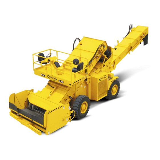
WEILER E1250 MACHINE TERMINOLOGY 1. Elevator 2. Remix Hopper 3. Conveyor 4. Operator Station 5. Dump Hopper 6. Engine and Pump Compartment 7. Battery Box... -
Page 8: Operator Station
WEILER E1250 OPERATOR STATION OPERATOR STATION - LOCATION AND FEATURES The operator station is located on the front upper platform. It offers the operator control and visibility of all operating functions Vandal Cover Picture and engine information needed in the operation of the machine. - Page 9 WEILER E1250 3. Propel Motor 2-Speed Switch (6) (High/Low)- Controls propel motor displacement. Move up for high and down for low. The Motor Speed Switches speed may be shifted while machine is in motion. An indicator light (7)is provided to indicate the motors are in high.
- Page 10 WEILER E1250 OPERATOR STATION - ENGINE CONTROLS 1. Ignition Switch (1) - The ignition switch is a key operated, three position rotary switch that controls engine starting, Key Switch and throttle stopping, and accessories. Vertical position is the OFF position.
- Page 11 WEILER E1250 OPERATOR STATION - ELEVATOR(TRUCK UNLOADING) CONTROLS 1.Elevator Switch- Turns on the elevator pump, causing the drag slat chain to turn in the forward direction. Move the switch up for on, down for off. Elevator switch, speed pot and...
- Page 12 WEILER E1250 OPERATOR STATION - CONVEYOR(PAVER LOADING) CONTROLS 1. Conveyor Switch-Turns on the conveyor pump, causing the drag slat chain to turn in the forward direction. Moving the Conveyor Controls switch up turn on the conveyor. 2. Conveyor Raise/Lower Switch- Raises and lowers the conveyor assembly.
-
Page 13: Dump Hopper Control Station
WEILER E1250 DUMP HOPPER CONTROL STATION DUMP HOPPER CONTROL STATION - LOCATION AND FEATURES The dump hopper control stations are provided at the rear of the dump hopper on the left and right hand side of the machine. Both Hopper Station Location stations are provided to allow a truck dump operator to dump trucks away from the lane of traffic. -
Page 14: Conveyor Service Control Station
WEILER E1250 CONVEYOR SERVICE CONTROL STATION CONVEYOR SERVICE CONTROL STATION - LOCATION AND FEATURES The conveyor service control station is provided for ease of cleanout for the operator. The station is conveniently located on Conveyor station LOCATION the right rear fender near the conveyor to allow for easy movement of the conveyor while washing down the machine. -
Page 15: Electrical Components
WEILER E1250 Electrical Components - Locations and Functions 1. Operators Station Circuit Breaker Panel Operator station CB Panel 2. Operators Station Circuit Breaker Decal 3. Cold Start Circuit Breaker - Located on the front side of the engine mounted to a bracket on the bell housing. -
Page 16: Engine Components
WEILER E1250 ENGINE COMPONENTS 1. Engine Oil Dipstick Front of Engine 2. Engine Oil Filter 3. Alternator 4. Starter 5. Turbo 6. Fuel Filter Rear of Engine 7. Fuel Water Separator Fuel Filter 8. Radiator Fill Radiator Fill CAUTION: Refill or check the radiator only when the engine is OFF. Turn cap slowly to the first stop to relieve the pressure before removing the cap, if engine is hot. -
Page 17: Hydraulic System
WEILER E1250 11. Fuel Tank Fuel Tank 12. Fuel Level Sender 13. Locking Fuel Cap HYDRAULIC SYSTEM CLUTCH AND PUMP DRIVE 1. Clutch Engagement Lever - Push towards the engine to engage. Pull away from the engine to disengage the clutch. - Page 18 WEILER E1250 5. Rear Ground Drive Pump Rear Ground Drive Pump Picture 6. Manual Overide - Rear Ground Drive Pump 7. System Pressure Test Port - Rear Ground Drive Pump. Pressure should measure 350psi in neutral, with 6090 psi MAX operating pressure.
- Page 19 WEILER E1250 PARK BRAKE/2-SPEED VALVE DANGER: Follow MachineTowing instructions regarding safe manual brake release. DO NOT ATTEMPT to manually release brakes until machine is properly secured, or machine may roll and cause injury. 1. Park Brake Release Spool Park Brake Valve 2.
- Page 20 WEILER E1250 ELEVATOR PUMP 1. Elevator Pump Elevator Pump 2. Manual Override - Elevator Pump 3. Charge Pressure Test Port Elevator Pump - Pressure should measure 350psi 4. Loop Flush Valve - Elevator Pump 5.Pressure Test Port Elevator Pump - Pressure should measure Loop Flush Valve 350psi in neutral, with 6090 psi MAX operating pressure.
- Page 21 WEILER E1250 CONVEYOR PUMP 1. Conveyor Pump Conveyor Pump 2. Manual Override - Conveyor Pump 3. Charge Pressure Test Port Conveyor Pump -Pressure should measure 350psi 4. Loop Flush Valve - Conveyor Pump Loop Flush Valve 5.Pressure Test Port Elevator Pump - Pressure should measure 350psi in neutral, with 6090 psi MAX operating pressure.
- Page 22 WEILER E1250 REMIX PUMP (Optional) 1. Remix Pump REMIX PUMP 2. Charge Pressure Test Port Remix Pump - Pressure should measure 300psi 3. Pressure Test Port Remix Pump - Pressure should measure 300psi in neutral, with 5000 psi MAX operating pressure.
- Page 23 WEILER E1250 ELEVATOR LIFT VALVE ELEVATOR LIFT VALVE Located on the front axle of the mainframe. 1. Elevator Raise/Lower Spool 2. Main System Relief Valve - Adjusts main system pressure. Relieves system pressure in the event of pressure compensator failure.
- Page 24 WEILER E1250 ELEVATOR DUMP HOPPER 1. Hopper Dump Cylinders DUMP HOPPER UP 2. Push Frame Extension Cylinder 3. Hydraulic Vibrator 4. Baffle Cylinder 5. Hopper Baffle BAFFLE CYLINDER 6. Hopper Cleanout Cylinder 7. Hopper Cleanout Door HOPPER CLEANOUT CYLINDER ELEVATOR 1.
- Page 25 WEILER E1250 CONVEYOR 1. Conveyor Lift Cylinder 2. Conveyor Swing Cylinder 3. Conveyor Clean Out Door CONVEYOR CYLINDERS 4.Conveyor Clean Out Door Cylinder STEERING 1. Steering Cylinder STEERING CYLINDERS 1-21...
- Page 26 WEILER E1250 GENERATOR (Optional) Generator Picture w/o cover 1. 9kW Generator - under cover 2. Generator Motor - under cover 3. Generator Flow Control Valve - used to set motor to 3600RPM. 4. Main Breaker - 30 Amp 5. Outlet Breakers - 20 Amp each 6.
-
Page 27: Machine Transporting
WEILER E1250 MACHINE TRANSPORTING SHIPPING Investigate the travel route for overpass clearances. Make sure there will be adequate clearance for the machine. Check state and local laws governing weight, width, and length of load. To prevent the machine from slipping while loading or shifting in transit, remove ice, snow, or other slippery material from the loading dock and the truck bed before loading. - Page 28 WEILER E1250 If it is necessary to build a ramp to unload the machine from a trailer, be certain to keep the ramp angle shallow enough so no part of the undercarriage of the machine will strike or hang up on the ramp. Also block sufficiently to support the weight of the machine, which at operating weight with water, fuel, lubricants and operator can be in excess of 50,000 pounds, depending on the options on the machine.
- Page 29 IMPORTANT: When transporting the machine on a trailer, always cover the exhaust outlet. Turbo charger damage may result if turbo charger turns without engine running. Contact your authorized Weiler dealer for further shipping instructions for your machine. 1-25...
-
Page 30: Machine Towing
WEILER E1250 MACHINE TOWING WARNING: Personal injury or death may result when towing a disabled machine incorrectly. WARNING: Block the wheels of the machine to prevent movement before attempting to release the brakes. When the brakes are released the machine can roll freely. -
Page 31: Section 2 - Operation
WEILER E1250 SECTION 2 - OPERATION BEFORE STARTING THE MACHINE MACHINE WALK-AROUND INSPECTION For maximum service life of the machine, make a thorough walk-around inspection before starting the engine. Look around and under the machine for loose bolts, asphalt build-up, oil or coolant leaks, and broken or worn parts. -
Page 32: Engine Starting
WEILER E1250 ENGINE STARTING PROCEDURE WARNING: DIESEL ENGINE EXHAUST CONTAINS PRODUCTS OF COMBUSTION WHICH MAY BE HARMFUL TO YOUR HEALTH. ALWAYS START AND OPERATE THE ENGINE IN A WELL VENTILATED AREA AND, IF IN AN ENCLOSED AREA, VENT THE EXHAUST TO THE OUTSIDE. - Page 33 WEILER E1250 3. Turn Main Power Switch (2) to ON position Ground disconnect switch 4. Verify that the Park Brake (3) is engaged, and all stop switches are pulled out. There are three stop switches, one on the main Park Brake and speed switches operators control panel and one on each of the dump hopper control panels.
-
Page 34: Driving The Machine
WEILER E1250 DRIVING THE MACHINE WARNING: CLEAR AREA AROUND MACHINE BEFORE MOVING. 1. Follow Engine Starting Procedure 2. Check to make certain PROPEL lever is in the NEUTRAL position. Place the propel motor high/ low switch (1) in LOW range. Place the propel creep switch in LOW range (2). -
Page 35: Machine Operation
7. Slowly raise the box on the dump truck until material ‘slides’ against the tailgate. Hold box at that height and unlatch tailgate, dumping material into the hopper of the E1250. If using a ‘flow boy’ truck or trailer fill the hopper by unloading material. - Page 36 WEILER E1250 10. At the end of each truck, after the truck is emptied, raise the dump hopper to transfer all of the materal. Use the vibrator to ‘shake’ loose any material that may be stuck to the hopper. Dumping the hopper will keep material from building up in the hopper and getting cool.
-
Page 37: Cleaning Stalled Machine
WEILER E1250 CLEANING STALLED MACHINE DANGER: NEVER USE TOOLS TO REMOVE MATERIAL FROM A STALLED MACHINE WITH THE ENGINE RUNNING. PERSONAL INJURY OR DEATH MAY RESULT. CAUTION: Asphalt is hot and will burn skin. Use caution when opening doors to not allow the asphalt to contact the skin. - Page 38 WEILER E1250 LOADING CONVEYOR In the event of a stalled loading conveyor use the following steps to remove material to free the slats. 1. Run the conveyor in reverse to remove material from the chute of the conveyor. It may be necessary to open the conveyor clean out door to allow material to discharge from the chute onto the ground.
- Page 39 WEILER E1250 5. Close clean out door, as described in the following steps. a. Lower the conveyor to the ground (until conveyor forces door to close), verify that there is not material keeping the door from closing, if so clean material out and reclose the door. Depending on the surface it may be necessary to back up the machine while lowering the conveyor.
-
Page 40: Machine Shutdown Procedure
WEILER E1250 MACHINE SHUT DOWN PROCEDURE 1. Turn Park Brake ‘ON’. 2. Shut off all functions: elevator, conveyor and generator. Place engine in idle, allow to idle for 2-3 minutes. 3. Place elevator and conveyor as low to the ground as possible. -
Page 41: Section 3 - Maintenance
Refer to the Engine Operation Manual supplied with the machine for information on maintaining the engine. • If a problem is encountered that is not understood or cannot be solved, contact your authorized WEILER dealer. • If removing a shield is necessary to perform maintenance, return it to its operating position before operating the machine. -
Page 42: Maintenance Intervals
WEILER E1250 MAINTENANCE INTERVALS The maintenance intervals outlined in the following maintenance section are based on normal operating conditions. When operating under severe conditions, the maintenance intervals should be shortened E1250 LUBRICATION CHART Interval - No. of Type of Reference... - Page 43 WEILER E1250...
-
Page 44: Chain Adjustment
WEILER E1250 CHAIN ADJUSTMENT ELEVATOR CHAIN 1. Open elevator clean out door, as described in the following steps. a. Lower elevator to ground (until stops (1) hit frame tube) b. Loosen clean out latches (2). c. Raise elevator to open door (3). - Page 45 WEILER E1250 3. Adjust chain as required by loosening the jam nuts (4) and tightening or loosening the take-up nuts (5) on both sides of the machine. Both sides of the chain should be adjusted to the same slack (+/- 1/8”).
- Page 46 WEILER E1250 CONVEYOR CHAIN 1. Open conveyor clean out door, as described in the following steps. a. Lower the conveyor to allow the cleanout door skid tubes (1) to be lowered to the down position. b. Lower the conveyor skid to the bottom set of holes (2) and place pin (3) in each side.
- Page 47 WEILER E1250 f.Move the conveyor chain so that there is a chain slat (6) just past the front edge of the cleanout door area. This allows for maximum ‘sag’ of the chain over the cleanout opening. 2. Chain slack in the door opening should be 1.25” below the bottom of the frame flange (+/- 1/4”) on the edge of the slat.
-
Page 48: Hydraulic Pressures
WEILER E1250 HYDRAULIC PRESSURE Ground Drive Pump- Front Charge Presure 350psi See page 1-13 for location System Pressure 350psi in Neutral See page 1-13 for locationl 6090psi Max Ground Drive Pump- Rear Charge Pressure 350psi See page 1-14 for location... -
Page 49: Battery Charging
Never short any of the charging components to ground. The E1250 uses a 24 volt system. Do not use a booster battery or charger of more than 24 volts. BATTERY CHARGING PROCEDURE - CHARGING AS 12V SYSTEM 1.Before charging the batteries, turn the master switch off and remove key to prevent others from activating any... -
Page 50: Welding
WEILER E1250 ALTERNATE BATTERY CHARGING PROCEDURE - CHARGING AS 12V SYSTEM An alternate way to charge batteries in a 24 volt system is to charge each battery alone as a 12 volt battery. This method is prefered by some. The steps for this process are detailed below: 1. -
Page 51: Section 4 - Receiving And Delivery Report
WEILER E1250 Receiving and Delivery Report DEALER PREP Check and perform the following: General ____ Check machine for shortage or damage in transit. ____ Check that all optional and loose items are included with the machine. ____ Record dealer information and serial numbers on back of front cover. - Page 52 WEILER E1250 Main Operator Control Station- Check Operation of the following: Engine Controls ____ Ignition switch ____ Engine speed switch ____ Engine tachometer ____ Engine oil pressure gauge ____ Engine water temperature gauge ____ Volt meter ____ Fuel level gauge...
- Page 53 WEILER E1250 Dump Hopper Control Station- Check Operation of the following: _____ Stop switch _____ Horn _____ Elevator raise/lower _____ Hopper baffle switch _____ Hopper dump switch _____ Hopper vibrator switch _____ Push roller adjustment switch _____ Hopper cleanout door...
- Page 54 WEILER E1250 This page intentionally left blank.
-
Page 55: Hydraulic Schematic
WEILER E1250 HYDRAULIC SCHEMATIC... - Page 56 WEILER E1250 HYDRAULIC SCHEMATIC...
- Page 57 WEILER E1250 HYDRAULIC SCHEMATIC...
- Page 58 WEILER E1250 HYDRAULIC SCHEMATIC...
- Page 59 WEILER E1250 ELECTRICAL SCHEMATIC ENGINE...
- Page 60 WEILER E1250 ELECTRICAL SCHEMATIC GROUND DRIVE...
- Page 61 WEILER E1250 ELECTRICAL SCHEMATIC ELEVATOR COVEYOR AND OPTIONAL REMIX HOPPER...
- Page 62 WEILER E1250 ELECTRICAL SCHEMATIC AUXILIARY FUNCTIONS...
Need help?
Do you have a question about the E1250 and is the answer not in the manual?
Questions and answers