
Related Manuals for Neousys Technology PB-9250J-SA

Summary of Contents for Neousys Technology PB-9250J-SA
- Page 1 Neousys Technology Inc. PB-9250J-SA/ PB-4600J-SA/ PB-2580J-SA User Manual Revision 1.5...
-
Page 2: Table Of Contents
Normal Backup Mode ..................28 3.1.2 Ignition Control Mode ..................29 3.1.3 Ignition Relay Mode ..................30 Daisy Chain Connection (PB-9250J-SA Only) ............31 Configuring Windows System ................. 32 CAP Energy Management Technology ~ Power Backup Parameter Configurer CAP Energy Management Technology ..............33 Power Backup Parameter Configurer .............. - Page 3 Table of Content 4.2.9 SuperCAP Lifetime Extension ................43 4.2.10 Operation Mode ....................44 4.2.11 IGN Setting ....................... 45 4.2.12 System Status Determined by ................46 4.2.13 Update Parameters ................... 47 4.2.14 Get Parameters ....................48 4.2.15 Load Default ...................... 48 4.2.16 Re-train ......................
-
Page 4: Legal Information
For questions in regards to hardware/ software compatibility, customers should contact Neousys Technology Inc. sales representative or technical support. To the extent permitted by applicable laws, Neousys Technology Inc. shall NOT be responsible for any interoperability or compatibility issues that may arise when (1) products, software, or options not certified and supported;... -
Page 5: Contact Information
Neousys Technology Inc. (Taipei, Taiwan) 15F, No.868-3, Zhongzheng Rd., Zhonghe Dist., New Taipei City, 23586, Taiwan Tel: +886-2-2223-6182 Fax: +886-2-2223-6183 Email, Website Americas Neousys Technology America Inc. 3384 Commercial Avenue, Northbrook, IL 60062, USA (Illinois, USA) Tel: +1-847-656-3298Email, Website China Neousys Technology (China) Ltd. -
Page 6: Copyright Notice
This manual is intended to be used as an informative guide only and is subject to change without prior notice. It does not represent commitment from Neousys Technology Inc. Neousys Technology Inc. shall not be liable for any direct, indirect, special, incidental, or consequential damages arising from the use of the product or documentation, nor for any infringement on third party rights. -
Page 7: Safety Precautions
Safety Precautions Safety Precautions Read these instructions carefully before you install, operate, or transport the system. Install the system or DIN rail associated with, at a sturdy location Install the power socket outlet near the system where it is easily accessible ... -
Page 8: Service And Maintenance
Service and Maintenance/ ESD Precautions Service and Maintenance ONLY qualified personnel should service the system Shutdown the system, disconnect the power cord and all other connections before servicing the system When replacing/ installing additional components (expansion card, memory module, etc.), insert them as gently as possible while assuring proper connector engagement ESD Precautions... -
Page 9: About This Manual
About This Manual About This Manual This manual introduces and demonstrates installation procedures of Neousys intelligent ultracapacitor-based power backup stand alone module, PB-9250J-SA, PB-4600J-SA and PB-2580J-SA. Revision History Version Date Description May. 2019 Initial release Updated SuperCap operation lifespan data in SuperCap Lifetime Jul. -
Page 10: Pb-9250J-Sa/ Pb-4600J-Sa/ Pb-2580J-Sa Overview
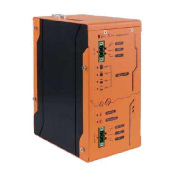
PB-9250J-SA/ PB-4600J-SA/ PB-2580J-SA Overview Introduction PB-9250J-SA, PB-4600J-SA and PB-2580J-SA are standalone power backup modules that can protect your box-PC against power outages. Utilizing state-of-the-art supercapacitor technology, it can operate in harsh environments from -25 to 65°C, and have extremely high durability lasting over 10 years. -
Page 11: Specification
** Backup time for uninterruptible operation may be reduced when sustaining a back-end system with high power consumption. *** To ensure PB-9250J and PB-4600J’s power backup operation functions as intended, please contact Neousys Technology technical support if your connecting back-end system accepts only constant voltage input. -
Page 12: Dimension
PB-9250J-SA/ PB-4600J-SA/ PB-2580J-SA Dimension NOTE All measurements are in millimeters (mm). 1.3.1 Main Panel View (Front View) PB-9250J-SA/ PB-4600J-SA PB-2580J-SA... -
Page 13: Com/ 10-Pin Io Panel View (Top View)
PB-9250J-SA/ PB-4600J-SA/ PB-2580J-SA 1.3.2 COM/ 10-Pin IO Panel View (Top View) PB-9250J-SA/ PB-4600J-SA PB-2580J-SA... -
Page 14: Din Rail View (Back View)
PB-9250J-SA/ PB-4600J-SA/ PB-2580J-SA 1.3.3 DIN Rail View (Back View) PB-9250J-SA/ PB-4600J-SA PB-2580J-SA... -
Page 15: Wall Mount View (Back View)
PB-9250J-SA/ PB-4600J-SA/ PB-2580J-SA 1.3.4 Wall Mount View (Back View) -
Page 16: Unpacking The System
PB-9250J-SA/ PB-4600J-SA/ PB-2580J-SA Unpacking the System Upon receiving and unpacking your PB-9250J-SA/ PB-4600J-SA, please check immediately if the package contains all the items listed in the following table. If any item(s)are missing or damaged, please contact your local dealer or Neousys Technology. -
Page 17: Main Panel I/O
PB-9250J-SA/ PB-4600J-SA/ PB-2580J-SA Main Panel I/O NOTE The PB series standalone supercapacitor UPS share the same connectivity, buttons, LED indicators and therefore PB-9250J-SA illustration will be used for demonstration purposes. Item Description Charging current selector switch for 5A or 10A. -
Page 18: 10A Charging Current Switch
PB-9250J-SA/ PB-4600J-SA/ PB-2580J-SA 2.2.1 5A/ 10A Charging Current Switch PB-9250J/ 4600J can be set to charge at 5A or 10A input. The different current input will result in different charging times from 0% to full. Please refer to the following table:... -
Page 19: 3-Pin Terminal Block For Dc/ Ignition Input
PB-9250J-SA/ PB-4600J-SA/ PB-2580J-SA 2.2.2 3-pin terminal block for DC/ ignition input The module accepts a wide range of DC power input from 12 to 35V via a 3-pin pluggable terminal block, which is fit for field usage where DC power is usually provided. The screw clamping mechanism on the terminal block offers connection reliability when wiring DC power. -
Page 20: Supercapacitor Energy Level
PB-9250J-SA/ PB-4600J-SA/ PB-2580J-SA 2.2.3 Supercapacitor Energy Level Color Status Description Steady-lid Energy of the SuperCAP reached 100% 100% Green Energy of the SuperCAP is below 100% Steady-lid Energy of the SuperCAP reached 75% Green Energy of the SuperCAP is below 75%... -
Page 21: Charging/ Discharging Status Led
PB-9250J-SA/ PB-4600J-SA/ PB-2580J-SA 2.2.4 Charging/ Discharging Status LED Color Status Description When lid, it indicates PB standalone module is being charged. Orange When flashing, it indicates a discharge status. -
Page 22: 3-Pin Terminal Block For Dc/ Ignition Output
PB-9250J-SA/ PB-4600J-SA/ PB-2580J-SA 2.2.5 3-pin terminal block for DC/ ignition output When charging, the system bypasses DC power output from 12 to 35V via a 3-pin pluggable terminal block. When discharging, the system provides 12/24 DC power output via a 3-pin pluggable terminal block. -
Page 23: Side Panel I/O
PB-9250J-SA/ PB-4600J-SA/ PB-2580J-SA Side Panel I/O Item Description 9-pin D-sub COM port to connect to the host RS-232 COM port computer. 10-pin input/ output terminal block consists of two 10-pin I/O terminal block signal pairs: power button signal output and system status input. -
Page 24: Com Port
PB-9250J-SA/ PB-4600J-SA/ PB-2580J-SA 2.3.1 COM Port The 9-pin D-sub COM port can connect and communicate with the host computer to acquire PB standalone module’s information. NOTE The host computer's COM port must be configured in RS-232 mode to properly communicate... -
Page 25: 10-Pin I/O Terminal Block
PB-9250J-SA/ PB-4600J-SA/ PB-2580J-SA 2.3.2 10-pin I/O Terminal Block There are two signal pairs on the 10-pin I/O terminal block. One is power button signal output (PWRBTN#), the other is system status input (SYS_STAT). Power button signal pair is sent by PB standalone module to turn on/off the back-end system. -
Page 26: Reset Button
PB-9250J-SA/ PB-4600J-SA/ PB-2580J-SA 2.3.3 Reset Button The reset button is used to manually reset and load system default configuration in case of a system halt or malfunction. To avoid unexpected operation, the button is purposely placed behind the panel. To reset the system, please use a pin to poke the button behind the panel... -
Page 27: Mode Configuration
PB-9250J-SA/ PB-4600J-SA/ PB-2580J-SA Mode Configuration Mode Connection PB standalone module can be configured to three different operating modes: Normal Backup Mode/ Ignition Control Mode/ Ignition Relay Mode. The following sections show detail information about how to connect and use the three different modes. -
Page 28: Normal Backup Mode
PB-9250J-SA/ PB-4600J-SA/ PB-2580J-SA 3.1.1 Normal Backup Mode Normal Backup Mode is for general purpose use of PB standalone module. In Normal Backup Mode, DC output 12~35V from power supply should be connected to the DC IN of PB standalone module. DC OUT of PB standalone module should be connected to the power input of the back-end system. -
Page 29: Ignition Control Mode
PB-9250J-SA/ PB-4600J-SA/ PB-2580J-SA 3.1.2 Ignition Control Mode Ignition Control Mode is ideal for box-PCs that lack the ignition control function, but still need and want to operate as an in-vehicle controller. With PB standalone module’s built-in IGN control function, the PB standalone module receives the IGN signal and sends a power button signal to the connected system. -
Page 30: Ignition Relay Mode
PB-9250J-SA/ PB-4600J-SA/ PB-2580J-SA 3.1.3 Ignition Relay Mode Ignition Relay Mode is for in-vehicle box-PCs in transportation application. In Ignition Relay Mode, the PB standalone module can receive IGN input signal and pass it to the back-end system. DC output 12~35V from power supply should be connected to the DC IN of the PB standalone module. -
Page 31: Daisy Chain Connection (Pb-9250J-Sa Only)
PB-9250J-SA/ PB-4600J-SA/ PB-2580J-SA Daisy Chain Connection (PB-9250J-SA Only) Daisy chain connection is only applicable to PB-9250J. PB-9250J can be wired together in sequence to extend energy capacity. To daisy chain PB-9250Js, user should connect DC power input into the first PB-9250J. Then connect the power output to next power input of PB-9250J, and so on. -
Page 32: Configuring Windows System
PB-9250J-SA/ PB-4600J-SA/ PB-2580J-SA Configuring Windows System Please make sure you’ve configured your Windows system to initiate a shutdown process when pressing the power button. By default, Windows 7/ 8/ 10 goes to sleep (S3) mode when the power button is pressed. As sleep (S3) is not a complete shutdown behavior, therefore the PB standalone module will not recognize this command. -
Page 33: Cap Energy Management Technology ~ Power Backup Parameter Configurer
PB-9250J-SA/ PB-4600J-SA/ PB-2580J-SA CAP Energy Management Technology ~ Power Backup Parameter Configurer By controlling fundamental techniques such as charge/ discharge control, active load balance and DC/ DC regulation, Neousys is able to design and create a reliable ultracapacitor-based power backup system. However, the real challenge is how to get the most out of the capacitor energy while ensuring the system shuts down safely during a power blackout. -
Page 34: Power Backup Parameter Configurer
PB-9250J-SA/ PB-4600J-SA/ PB-2580J-SA Power Backup Parameter Configurer 4.2.1 Executing Power Backup Parameter Configurer The Power Backup Parameter Configurer is an application that allows the user to monitor and manage the connected the PB standalone module. Once you have setup the PB standalone module and have connected it to the host controller COM port (configured in RS-232 mode). -
Page 35: Connecting To A Different Com Port On Host Computer
PB-9250J-SA/ PB-4600J-SA/ PB-2580J-SA 4.2.3 Connecting to a Different COM Port on Host Computer If you wish to connect to another COM port (COM2, 3 or 4), you will need to reconfigure the connection setting or the configurer will read false readings (F/W Version, DC Voltage, CAP Energy) upon initial connection. - Page 36 PB-9250J-SA/ PB-4600J-SA/ PB-2580J-SA Type in “PB_Configurer.J25.19.exe com3” (.exe file name + COM port number connected) and press Enter. Once the command has been issued, all parameters should be updated accordingly. If not, press “Get Parameters” on the configurer to acquire statuses.
-
Page 37: Power Backup Parameter Configurer Overview
PB-9250J-SA/ PB-4600J-SA/ PB-2580J-SA 4.2.4 Power Backup Parameter Configurer Overview Item Description DC Voltage Shows the current input voltage of your PB-9250J. CAP Energy Shows the current charged energy status (rated 9250Ws Max.). Power Output Shows the power draw of the back-end system. - Page 38 PB-9250J-SA/ PB-4600J-SA/ PB-2580J-SA shutdown the system when the PB standalone module is configured in Ignition Control Mode. Power Out Determines back-end system status via power draw/ consumption of back-end system. User can define the maximum standby power draw/ consumption SUS__W of the connected PC (ex.
-
Page 39: Behavior When Power Applied
PB-9250J-SA/ PB-4600J-SA/ PB-2580J-SA 4.2.5 Behavior when Power Applied Behavior when Power Applied Auto-start when If the “Auto-start” box is checked, the system will start after the PB Power applied standalone module has been fully charged when DC applied. If the “Auto-start” box is not checked, once you have plugged in the... -
Page 40: Behavior When Power Loss
PB-9250J-SA/ PB-4600J-SA/ PB-2580J-SA 4.2.6 Behavior when Power Loss Behavior when Power Loss Settings Auto If the “Auto” box is selected, the delay shutdown time will be pre-determined by the MCU when you “Re-train” the PB standalone module. User-defined If the “User-defined Shutdown after _ seconds” is selected, when... -
Page 41: Shutdown At Low Voltage
PB-9250J-SA/ PB-4600J-SA/ PB-2580J-SA 4.2.7 Shutdown at Low Voltage Shutdown at low Voltage Enable If the “Enable” box is checked, the shutdown process will be determined by the Low Limit: _ V and Delay: _ seconds settings. Low Limit: _ V If the “Enable”... -
Page 42: Shutdown At High Voltage
PB-9250J-SA/ PB-4600J-SA/ PB-2580J-SA 4.2.8 Shutdown at High Voltage Shutdown at High Voltage Enable If the “Enable” box is checked, the shutdown process will be determined by the High Limit: _ V and Delay: _ seconds settings. High Limit: _ V If the “Enable”... -
Page 43: Supercap Lifetime Extension
PB-9250J-SA/ PB-4600J-SA/ PB-2580J-SA 4.2.9 SuperCAP Lifetime Extension The SuperCAP lifetime extension setting is an automated setting when users only need to click on the bar, drag it to the desired lifetime extension setting, click on the “Update Parameters” and follow procedure instructions for settings to take effect. -
Page 44: Operation Mode
PB-9250J-SA/ PB-4600J-SA/ PB-2580J-SA 4.2.10 Operation Mode Operation Mode Normal Backup If “Normal Backup Mode” box is selected, PB standalone module Mode will operate in Normal Backup Mode. Ignition Control If “Ignition Control Mode” box is selected, PB standalone module Mode... -
Page 45: Ign Setting
PB-9250J-SA/ PB-4600J-SA/ PB-2580J-SA 4.2.11 IGN Setting If the PB standalone module is in Ignition Control Mode, user can set IGN on/off delay via IGN setting. On-delay The PWRBTN# signal will be sent after _ seconds (Delay: _ seconds) after (sec) the PB standalone module is fully charged to turn on the back-end system. -
Page 46: System Status Determined By
PB-9250J-SA/ PB-4600J-SA/ PB-2580J-SA 4.2.12 System Status Determined by The PB standalone module has to monitor back-end system status (whether it’s on or off) in order to make the right operation in different situation. Power Out System status is determined by the power draw/ consumption of back-end system. -
Page 47: Update Parameters
PB-9250J-SA/ PB-4600J-SA/ PB-2580J-SA 4.2.13 Update Parameters Whenever you enter/ adjust a new parameter or parameters, for the new settings to take effect, you must perform the following steps: Click on the “Update Parameters” button and the following dialogue will appear. -
Page 48: Get Parameters
PB-9250J-SA/ PB-4600J-SA/ PB-2580J-SA 4.2.14 Get Parameters Click on “Get Parameters” to manually acquire the current the PB standalone module status for DC voltage, current stored CAP energy and power output. 4.2.15 Load Default You may set the PB standalone module back to the original settings by clicking on “Load... -
Page 49: Re-Train
PB-9250J-SA/ PB-4600J-SA/ PB-2580J-SA 4.2.16 Re-train The Re-train function is to customize the PB standalone module to your system’s required shutdown time! By clicking on “Re-train”, a shutdown action will be initiated so the time required to shutdown can be memorized. -
Page 50: Estimated Extended Operation Time
Using PB-9250J-SA as an example, below is an estimated extended operation time one can expect for the connected back-end system during unforeseen power outage events. The actual extended operation time may vary depending on your connected back-end system hardware configuration.
Need help?
Do you have a question about the PB-9250J-SA and is the answer not in the manual?
Questions and answers