Table of Contents
Advertisement
Quick Links
1 General
1.1 About this Handbook
This handbook describes the servo amplifiers for the DIAS-Drive
series. You will find additional information on the safety functions
and the existing inputs and outputs in the used VAC 013 inter-
face module in the according chapter.
The individual chapters:
•
Technical Data
•
Assembly and Installation
•
Description of interfaces
•
Servo Amplifier settings
•
Accessories
•
Transport, Storage, Maintenance, Disposal
Abbreviations used in this handbook
Abbreviation
AWG
BGND
CE
CLOCK
EMV
EN
IGBT
LED
PELV
RES
R
int.
R
tr
V AC
+24 V DC
30.03.2021
Definition
American Wire Gauge
Mass for the 24 V auxiliary and braking supply
Communité Europeenne
Clock signal
Electromagnetic tolerance
European Norm
Insulated Gate Bipolar Transistor
Light emitting diode
protected Extra Low Voltage
Resolver
Internal brake resistor connection
Brake chopper connection
Alternating current
Direct current
DIAS-DRIVE 210-23
Page 1
Advertisement
Table of Contents

Subscribe to Our Youtube Channel
Summary of Contents for SIGMATEK DIAS-DRIVE 210-23
- Page 1 DIAS-DRIVE 210-23 1 General 1.1 About this Handbook This handbook describes the servo amplifiers for the DIAS-Drive series. You will find additional information on the safety functions and the existing inputs and outputs in the used VAC 013 inter- face module in the according chapter.
- Page 2 DIAS-DRIVE 210-23 General About this Handbook Abbreviations used in this handbook Safety Guidelines Servo Amplifier Components European Guidelines and Standards Designated Use Non-Designated Use Block Diagram Technical Data 1.10 Environmental conditions, Ventilation and Mounting 19 1.11 Auxiliary supply voltage Installation...
- Page 3 DIAS-DRIVE 210-23 Maintenance Exchange and Repair Appendix Transport, Storage and Disposal Correcting Errors 5.2.1 LED Display 5.2.2 Amplifier Malfunctions 5.2.3 Status Register DIAS Drive Accessories Shielding Plate with Strain Relief 6.1.1 Mounting Instructions Mounting Set 6.2.1 Mounting Instructions Dimensions VARAN Interface for the DIAS Drive 3xx (VAC 013)
- Page 4 DIAS-DRIVE 210-23 1.2 Abbreviations used in this handbook Danger! Electric Shock Danger of electric shock Warning! General Danger posed by machines, general warning Warning! Hot Surface Temperatures over 80°C (176°F) Important Note See handbook Page 4 30.03.2021...
-
Page 5: Safety Guidelines
DIAS-DRIVE 210-23 1.3 Safety Guidelines Before installation and startup, it is important to read the documenta- tion provided. Incorrect handling of the servo amplifier can lead to per- sonnel injury or material damage. The technical data and connection instructions (specification label and documentation) must be followed. - Page 6 DIAS-DRIVE 210-23 When using a ground fault interrupter in the circuit, a type B FI-switch must be used. If a type "A" FI-switch of is used, a DC ground fault could cause a malfunction. Failure to follow these instructions can lead to death, serious injury or damage to the machine.
- Page 7 DIAS-DRIVE 210-23 CAUTION! Hot surface During operation, the heat sink of the servo amplifier can reach temperatures of over 80° C (176° F). The heat sink temperature should be checked before handling and it may be necessary to wait until it is below 40° C (104° F).
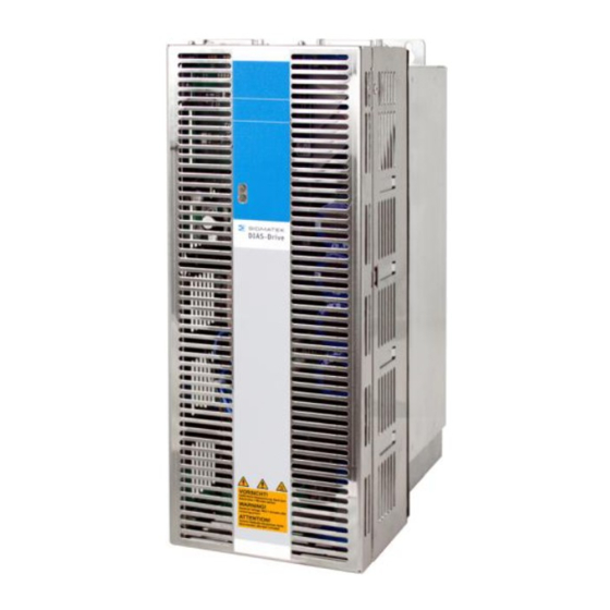
- Page 8 DIAS-DRIVE 210-23 1.4 Servo Amplifier Components Page 8 30.03.2021...
- Page 9 DIAS-DRIVE 210-23 1.5 European Guidelines and Standards Servo amplifiers and components, which are designed for installation in electrical sys- tems/machines for industrial use. With the installation into machines/systems, the servo amplifier should not be operated until it has been determined that the machine/system meets the requirements of the machine guideline 2006/42/EC and the EMV guideline 2014/30/EU.
-
Page 10: Designated Use
DIAS-DRIVE 210-23 1.6 Designated Use The servo amplifier from SIGMATEK GmbH & Co KG was designed and produced with state of the art technology. The product was tested for reliability before delivery. It is an installed component for electrical systems and can only be operated as an integral part. -
Page 11: Non-Designated Use
DIAS-DRIVE 210-23 1.7 Non-Designated Use If a servo amplifier is operated according to the environmental conditions described in this document, it is "designated use". • Single-phase operation is not authorized as standard use, but is al- lowed for initial startup and demonstration purposes. -
Page 12: Block Diagram
DIAS-DRIVE 210-23 1.8 Block Diagram Page 12 30.03.2021... - Page 13 DIAS-DRIVE 210-23 Hardware • The main supply is connected to a rectifier, input filter and a load cir- cuit, which reduces the load current for the electrical torque. • IGBT – Power output stage with separate current measurement (short circuit protected).
- Page 14 DIAS-DRIVE 210-23 DIAS-Drive Concept • 1 and 3-axis amplifiers to reduce machine costs. 3-axis amplifiers have advantages through components savings • Auto-range function to optimize the resolution of the actual current of 10 A axes, in various configurations. • Two different mounting options.
- Page 15 DIAS-DRIVE 210-23 Software functions • Modified space vector modulation (SVM) technology to reduce power output loss. • Field oriented current regulator (update every 62.5 µs) • Feedback evaluation and speed controller (update every 62.5µs) • Spline interpolation and position controller (update every 62.5µs) •...
-
Page 16: Technical Data
DIAS-DRIVE 210-23 1.9 Technical Data DIAS-Drive SDD 210-23 Rated values Rated input voltage (symmetrical 3 x 230V-10% - 480V 10% , 45 – 65 Hz opposite to earth) max. 5000 Aeff. (L1, L2, L3) Max. peak current in electrical torque (limited by the load circuit) - Page 17 DIAS-DRIVE 210-23 PWM frequency Regulator frequency Brake unit Capacitance of the intermediate µF circuit voltage Ω External brake resistance 25 - 50 Ω Internal brake resistance Rated power of the internal brake resistor G-VMAINS =230 (rated supply voltage = 230V)
- Page 18 DIAS-DRIVE 210-23 Connector types Internal auxiliary power supply (X1A) Combicon 5, 3-pin, 2.5mm² Power supply (X1B) Power Combicon 7.62, 8-pin, 4mm² Feedback (X6, X8) Sub-D 25-pin (female) Motor (X3, X5) Power Combicon 7.62, 6-pin, 4mm² Dimensions Height with/without connector plugs...
-
Page 19: Auxiliary Supply Voltage
DIAS-DRIVE 210-23 1.10 Environmental conditions, Ventilation and Mounting Storage conditions Page 50 Transport conditions Page 50 Operational environmental conditions 0 to +45°C (32 to 113°F) at rated values +45 to 55°C (113 to 131°F) at power reduction by 2.5% / K... -
Page 20: Installation
DIAS-DRIVE 210-23 2 Installation 2.1 Important Guidelines • When using a ground fault interrupter in the circuit, a type B FI-switch is required. If an FI switch of type "A" is used, A DC ground fault could cause it to malfunction. High-frequency leakage currents occur, which must be taken into consideration when selecting the FI (e.g. - Page 21 DIAS-DRIVE 210-23 • The main supply can under no circumstances exceed the rated values for the servo amplifier. Attention should be paid to "Different Power supplies" on page 3029. • The external fuse for the main supply, the +24 V auxiliary and holding brake supply must meet the specifications for "External Fuse"...
- Page 22 DIAS-DRIVE 210-23 2.2 Configuration of the Control Cabinet 2.2.1 Wiring Diagram and Pin Layout Page 22 30.03.2021...
- Page 23 DIAS-DRIVE 210-23 SDD 210-23 Amplifier type Axis 1 Axis 2 Cable Motor Feedback Motor Feedback SDD210-23 30.03.2021 Page 23...
- Page 24 DIAS-DRIVE 210-23 2.2.2 Mechanical Construction and Mounting The control shows the servo amplifier dimensions . Page 24 30.03.2021...
- Page 25 DIAS-DRIVE 210-23 Cable duct Cable duct The cable channels below and above the servo amplifier must have the specified distances. This will ensure the sufficient air reaches the heat sink. Material: 4 x M5 socket head screws DIN 912 Required tool:...
- Page 26 DIAS-DRIVE 210-23 2.2.3 Laying the motor and control cables Note: the motor and control cable must be kept separate. The voltage con- nection to X1B should also be laid mainly in the cable channels on the left side of the control cabinet.
-
Page 27: Connector Layout
DIAS-DRIVE 210-23 Connector Layout 2.2.4 All connections to the servo amplifier are plug connectors (except: grounding bolts). With this method, the cable connection is simplified and the amplifier can be more easily ex- changed. In addition, the option is provided to produce prefabricated cable sets for high machine volumes. -
Page 28: External Fuse
DIAS-DRIVE 210-23 2.2.6 External Fuse The AC and 24V fuse are designed according to the customer requirements for the circuit. Signal Fuses, inertia The size of the fuse depends on the average power consump- AC voltage supply (L1-L3) tion of the connected amplifier. Max. 20 A with 4 mm... - Page 29 DIAS-DRIVE 210-23 2.2.7 Voltage Supply Options The main voltage supply for the DIAS-Drive requires a fixed connection. If the servo amplifier is mounted with a connector terminal to a moving machine part, the ground connection must have a cross section of at least 10 mm² (8 AWG) to avoid the high residual current (>3.5 mA).
- Page 30 DIAS-DRIVE 210-23 NOTE: non-earthed main voltage supplies al- ways required additional overvoltage protection. Power supply If the input supply voltage exceeds the specified maximum value, a suitable transformer is required to reduce it. Page 30 30.03.2021...
- Page 31 DIAS-DRIVE 210-23 2.2.8 Using Cooling Devices The Servo amplifier functions up to an ambient temperature of 45° C (55° C with reduced power). Under some circumstances, a cooling device is required. NOTE: A cooling device always produces condensation water. The following points must therefore be observed: •...
- Page 32 DIAS-DRIVE 210-23 Condensation water can also be avoided as follows • The switch point of the temperature regulator should be just below the building temperature. • In damp environments, the proper seals should be used in the con- trol cabinet.
- Page 33 DIAS-DRIVE 210-23 2.2.9 Turn on/off response of the servo amplifier The turn on/off response of the servo amplifier is shown below. 24V – Auxiliary supply Max. 15 s Amplifier drive ready “ Main con tact L1, L2, L3 Under voltage Max.
- Page 34 DIAS-DRIVE 210-23 2.2.10 Stop Brake Control +24V_BR Min. 0.2 sec Min. 0.1 sec Enable Speed Setpoint Host Speed Setpoint Emergency ramp internally Brake enable delay time Actual Max. 1 sec Speed Speed threshold Enable internally Brake disable delay time Brake...
- Page 35 DIAS-DRIVE 210-23 3 Connections 3.1 Main Power supply (X1B) The connection to the main supply voltage is designed for voltages from 230 V to 489 V AC. When using a non grounded supply, over voltage protection must be built into the main power supply of the control cabinet.
- Page 36 DIAS-DRIVE 210-23 3.2 24 V Auxiliary supply – Stop Brake Supply (X1A) If a 24 V supply is used in the control cabinet to power the relays, coils or other devices, it can also be used for the servo amplifier (the maximum current of the supply must be taken into consideration).
- Page 37 DIAS-DRIVE 210-23 3.3 DC-link (X1B) To bridge the intermediate circuit voltage with other servo amplifiers, the X1B/2 (+DV) and 3 (-DC) connectors can be used. The power from the intermediate circuit of different servo amplifiers can be distributed using the method.
- Page 38 DIAS-DRIVE 210-23 3.4 External brake resistance (X1B) If the power of the internal brake resistor is insufficient, an external resistor can be added. Here, the connection between R (terminal 4 of X1B) and R (terminal 5 of X1B) must be removed.
- Page 39 DIAS-DRIVE 210-23 3.5 Motor connections (X3, X5) 3.5.1 Standard configuration The cable length for the motor is limited to 25 m. If a longer cable is used, additional sup- pression coils in the motor output are required. 30.03.2021 Page 39...
- Page 40 DIAS-DRIVE 210-23 3.5.2 Classic Emergency-Stop (Stop-Category 0) The cable length for the motor is limited to 25 m. If a longer cable is used, additional sup- pression coils in the motor output are required. Note: The KEM coil must be turned on before the amplifier is enabled and can be turned off after at least 1 ms after the amplifier is "disabled.
- Page 41 DIAS-DRIVE 210-23 3.5.3 Personnel-Safe Stop Brake Control The servo amplifier has high brake control reliability. If a personnel-safe stop brake control is required, an additional safety contact in the +24V- BR voltage path is needed that complies with safety standards.
- Page 42 DIAS-DRIVE 210-23 3.6 Feedback (X6, X8) The servo amplifier has various feedback inputs for different feedback devices. • Resolver Feedback with thermo contacts • ® EnDAT encoder (single and multiturn) • ® Hiperface encoder (single and multiturn) • Sin/Cos & TTL Encoder For EnDAT, Hiperface, Sin/Cos and TTL a maximum number of 8192 feedback signals per mechanical rotation is supported (M-RPULSE).
-
Page 43: Resolver Feedback
DIAS-DRIVE 210-23 3.6.1 Resolver Feedback A Resolver is used as the standard feedback. The Servo amplifier supports the analysis of single-speed (2-pin) and multi-speed Resolvers (up to 32 pins). The maximum cable length is 50 m. If a thermo contact is used, the signal is also wired into the Resolver cable. - Page 44 DIAS-DRIVE 210-23 ® 3.6.2 EnDAT Signal Encoder One of the high resolution feedback systems for servo motors is the encoder with EnDAT interface. The cable length is limited to 25 m. If a thermo contact is used, the signal is transmitted through the feedback cable.
- Page 45 DIAS-DRIVE 210-23 ® 3.6.3 Hiperface Signal Encoder ® The signal encoder with a Hiperface® or Interfaceis a high-resolution feedback system for motors. The cable length is limited to 25 m. 30.03.2021 Page 45...
- Page 46 DIAS-DRIVE 210-23 3.6.4 Sine/Cosine & TTL Encoder feedback A sine encoder is a high-resolution feedback system, used with linear or torque servomo- tors. The maximum cable length is limited to 10 m. If a thermal contact is used in the motor, the signal is also connected via the encoder cable.
-
Page 47: Maintenance
DIAS-DRIVE 210-23 4 Maintenance The servo amplifier is maintenance-free. Note: Opening the housing results in the loss of warranty. Dirt on the housing can be removed with isopropyl alcohol or similar prod- ucts. • Contamination in the device must be removed by the manufacturer. - Page 48 DIAS-DRIVE 210-23 Disconnect the plug contact. The connectors should be labeled to avoid confusing them later. The servo amplifier can be dismantled. The replacement unit must be compared with the original amplifier; only identical amplifiers can be used. Reestablish the connection. The connectors must not be crossed.
-
Page 49: Transport, Storage And Disposal
DIAS-DRIVE 210-23 5 Appendix 5.1 Transport, Storage and Disposal Transport: • For transport, the original recyclable packaging from the manufactur- er must be used. • During transport dropping should be avoided. • The storage temperature must be between –25 to +70° C (-13...158°... - Page 50 DIAS-DRIVE 210-23 • A maximum of 6 servo amplifiers can be stacked on top of one an- other. • The storage temperature must be between –25 to +70°C (- 13...158°F), change max. 20K/h. • The maximum humidity is 95%, non-condensing.
-
Page 51: Correcting Errors
DIAS-DRIVE 210-23 5.2 Correcting Errors Errors and warnings are indicated by LEDs and displayed over the bus system. On page 53 under "Status Register", the various errors that can occur are described. 5.2.1 LED Display The DIAS-Drive DIAS-Driveshows the actual amplifier status through two LEDs... - Page 52 DIAS-DRIVE 210-23 5.2.2 Amplifier Malfunctions Amplifier Malfunctions Possible Causes: Solution ─ When the motor is turning ─ Resolver does not func- ─ Check Resolver in the clockwise direction tion correctly ─ Connect Resolver according to (observe the motor shaft) ─ Resolver connected...
-
Page 53: Status Register
DIAS-DRIVE 210-23 5.2.3 Status Register With I-STATUS, the status of the DIAS-Drive can be read. In a 32-bit variable, all error and status information is contained. The amplifier response can be changed by setting the ap- propriate bits in the G-MASKE1, G-MASKE2, G-MASKW and G-MASKD functions. - Page 54 DIAS-DRIVE 210-23 ─ Defective internal stop ─ exchange the amplifier Brake switch error brake switch ─ No stop brake connected ─ Motor used with stop brake ─ Change M-BRAKE parameter with parameters M-BRAKE = 1 to 0 as long as a motor without brakes is used.
- Page 55 DIAS-DRIVE 210-23 ─ No new values were ─ Synchronization is not engaged, Host communica- tion transmitted for two suc- check A-CTIME and the cycle cessive cycles time of the control ─ Check A-STIME ─ Internal communication ─ Communication interrupted, error with the interface check ─...
- Page 56 DIAS-DRIVE 210-23 ─ For motors with EnDAT ─ Encoder was not loaded with M ® Motor parameter ® error HIPERFACE encoders, - parameters. ─ Encoder defective. no M - parameters were ─ Signal lines or connector defec- found in the encoder.
-
Page 57: Mounting Instructions
DIAS-DRIVE 210-23 6 DIAS Drive Accessories 6.1 Shielding Plate with Strain Relief (Article number: 09-501-101-Z1) The shielding plate with strain relief serves for the protection of the cable of the DIAS Drive. Included in delivery are: 1 pcs. Strain relief... -
Page 58: Mounting Set
DIAS-DRIVE 210-23 6.2 Mounting Set (Article number: 09-501-101-Z2) The mounting set serves as a mount in the control cabinet for the DIAS Drive. The position of the drive's fan block is located on the outside of the control cabinet (better ventilation). - Page 59 DIAS-DRIVE 210-23 6.2.1 Mounting Instructions Mounting on the upper side of the drive. Place the mounting bracket in the provided slots and secure both screws. Mounting on the under side of the drive. Place the mounting bracket in the provided slots and secure both screws.
- Page 60 DIAS-DRIVE 210-23 6.3 Dimensions Page 60 30.03.2021...
- Page 61 DIAS-DRIVE 210-23 7 VARAN Interface for the DIAS Drive 3xx (VAC 013) This VARAN interface module is used for communication between a DIAS drive and a con- trol over the VARAN bus. It is integrated into the DIAS Drive. It contains the safety functions SS1 (Safe Stop 1) (stop category 1 according to EN60204) for safely shutting down the amplifier and the "safe restart"...
- Page 62 DIAS-DRIVE 210-23 7.1 Technical Data General Interface connections 1 x VARAN-In (RJ45) (maximum length: 100 m) 1 x VARAN-Out (RJ45) (maximum length: 100 m) 1 x DIAS-Drive interface (26-pin blade terminal) 4 fast digital inputs 2 safety inputs for the SSI (SAFE Stop 1) and STO (SAFE Torque Off) safety functions.
- Page 63 DIAS-DRIVE 210-23 Relay specifications Number of relays 1 x Relay output (contacts S3, S4) Relay types 1 x normally open Power supply +24 V DC Switching time <10 ms Switching range Max. 30 V DC/ min. 100 µA, max. 0.5 A Switching power Max.
- Page 64 DIAS-DRIVE 210-23 Environmental conditions -20 – +85 °C Storage temperature 0 … +45 °C with derating up to 55 °C, see chapter 1.10 Operating temperature Humidity 0 - 95 %, uncondensed EMV stability Tested in the DIAS Drive according to EN61800-3...
-
Page 65: Mechanical Dimensions
DIAS-DRIVE 210-23 7.2 Mechanical Dimensions Integrated into the SDD3xx servo amplifier 30.03.2021 Page 65... - Page 66 DIAS-DRIVE 210-23 7.3 Connector Layout X1: VARAN-In Function TX/RX+ TX/RX- RX/TX+ 4 – 5 RX/TX- 7 – 8 X2: VARAN-Out Function TX/RX+ TX/RX- RX/TX+ 4 - 5 RX/TX- 7 - 8 Further information about the VARAN bus can be found in the VARAN bus specifica-...
- Page 67 DIAS-DRIVE 210-23 X3: IO Function ENABLE_L ENABLE_H Reserved Reserved Not used Not used Reserved Reserved Reserved Ext. GND D-IN 1 D-IN 2 D-IN 3 D-IN 4 Applicable connectors X3: 2 x 8-pin Phoenix plug with spring terminal FMC1, 5/8-ST-3.5 For the stress relief, it is important to ensure that the minimum bend radius (eight times the cable diameter) of the cable is not exceeded! 30.03.2021...
-
Page 68: Status Displays
DIAS-DRIVE 210-23 7.4 Status Displays LED color Definition Green LINK Lights when the connection between the two PHYs is established VARAN IN Yellow ACTIVE Lights when data is received or sent over the VARAN bus. Green LINK Lights when the connection between the two PHYs is established. -
Page 69: Additional Safety Information
DIAS-DRIVE 210-23 7.5 Additional Safety Information The safety module "Safe Restart Lock" in an integral component of the DIAS Drive 3xx and is already installed with delivery; it meets the conditions required for safe operation accord- ing to SIL 3 in compliance with IEC 62061 and according to PL e in compliance with EN 13849-1. - Page 70 DIAS-DRIVE 210-23 • Only qualified personnel are authorized to install the "safe restart" STO (Safe Torque off) and set the parameters. • All control devices (switches, relays, PLC, etc.) and the control closet must meet the requirements for EN 13849 This consists of: –...
-
Page 71: Additional Information
DIAS-DRIVE 210-23 7.6 Additional Information 7.6.1 "Safe Restart" STO (Safe Torque Off) The DIAS Drive, in combination with the optional VARAN interface, supports the safety functions SS1 (Safe Stop 1) and STO (Safe Torque Off), and meets the requirements for Category 4 Performance Level "e"... - Page 72 DIAS-DRIVE 210-23 Implementation The following block diagram gives an overview of the internal switching circuit. REL 01 G 01 OPTO 01 CONTR 01 AMP 01 Super visor Astable Multi- U_Treiber vibrator OPTO 02 Super 0.5s visor AMP 02 Control CONTR 02...
- Page 73 DIAS-DRIVE 210-23 Blocks AMV, OPTO 01 and OPTO 02 As long as the AMV block is powered by the IN input block, it generates a pulse with a constant frequency that is transmitted to the sequential electronics through blocks OPTO 01 and OPTO 02.
- Page 74 DIAS-DRIVE 210-23 Function The safety functions in the DIAS Drive are controlled over two digital inputs. The following table shows the status that the ENABLE_L and ENABLE_H inputs must as- sume to enable normal operation or trigger the safety function.
- Page 75 DIAS-DRIVE 210-23 Software Enable ENABLE_H – ENABLE_L >= 15V STO aktivated SS1 aktivated Enable (internally) Speed set point of the controller G-EMRAMP Actual speed max. 1 s Timing Diagram If the ENABLE_L and ENABLE_H are changed from any status to the "Drive Ready" status, the servo amplifier is not immediately enabled.
- Page 76 DIAS-DRIVE 210-23 Function Test The safety function test is required to ensure correct operation. The entire safety circuit must be tested for full functionality. Tests must be performed at the following times: • After installation • In regular intervals, or at least once a year.
- Page 77 DIAS-DRIVE 210-23 Example Connection with Switching Contacts To meet the requirements of safety category 4, performance level "e" for EN 13849-1 and SIL3 according to EN 62061, a two-channel control must be provided for the safety func- tions. The wiring for both connections must be provided with protective insulation (to avoid the "external voltage supply"...
- Page 78 DIAS-DRIVE 210-23 Example: Safety PLC Application To meet the requirements of safety category 4, performance level "e" for EN 13849-1 and SIL 3 according to EN 62061, an error-proof output of a safety PLC must be used. There are two Types of error-safe outputs.
- Page 79 DIAS-DRIVE 210-23 30.03.2021 Page 79...
- Page 80 DIAS-DRIVE 210-23 Two-channel error-proof relay output, with which the + output is connected to ENABLE_H and the – output to ENABLE_L. Page 80 30.03.2021...
- Page 81 DIAS-DRIVE 210-23 30.03.2021 Page 81...
- Page 82 DIAS-DRIVE 210-23 7.7 Addressing Description Reset value Axis 1 Transmit Execution Register Bit 0: 1 = Start Object Transfer 0000 Bit 1: 1 = Repeat Object Transfer Bit 2: 1 = Enable Value 3-5 Bit 3…7: Reserved 0001 Reserved 0002...
- Page 83 DIAS-DRIVE 210-23 Axis 2 Transmit Execution Register Bit 0: 1 = Start Object Transfer 0040 Bit 1: 1 = Repeat Object Transfer Bit 2: 1 = Enable Value 3-5 Bit 3…7: Reserved 0041 Reserved 0042 Drive Control Byte 0043 Object Address...
- Page 84 DIAS-DRIVE 210-23 0083 Object Address 0084 Object Value 00000000 0088 Value 1 00000000 008C Value 2 00000000 0090 Value 3 00000000 0094 Value 4 00000000 0098 Value 5 00000000 009C Reserved 00000000 Receive Status Register Bit 0: 1 = Executed Object Transfer...
- Page 85 DIAS-DRIVE 210-23 00E1 reserved 00E2 Digital In/Out Byte 00E3 Transmit Control Byte 00E4 Value 8 00000000 00E8 Value 9 00000000 00EC Value 10 00000000 00F0 reserved For additional addressing, see the VARAN bus specifications More addressing applications can be found in the DIAS drive parameter documenta- tion.
- Page 86 Especially when for structural reasons, the bus line must be placed next to strong electromagnetic interference. SIGMATEK recommends the use of CAT5e industrial Ethernet bus cables. For the shielding, an S-FTP cable should be used. An S-FTP bus is a symmetric, multi-wire cable with unshielded pairs. For the total shielding, a combination of foil and braiding is used.
- Page 87 DIAS-DRIVE 210-23 7.8.1 Wiring from the Control Cabinet to an External VARAN Component If the Ethernet lines are connected from a VARAN component to a VARAN node located outside the control cabinet, the shielding should be placed at the entry point to the control cabinet housing.
-
Page 88: Wiring Outside Of The Control Cabinet
DIAS-DRIVE 210-23 7.8.2 Wiring Outside of the Control Cabinet If a VARAN bus cable must be placed outside of the control cabinet only, no additional shield connection is required. This requires that only IP67 modules and connectors be used. These components are very robust and noise resistant. The shielding for all sockets in IP67 modules are internally connected to common bus or electrically connected to the housing, whereby the deflection of voltage spikes does not flow through the electronics. - Page 89 DIAS-DRIVE 210-23 7.8.3 Shielding for Wiring Within the Control Cabinet Sources of strong electromagnetic noise located within the control cabinet (drives, Trans- formers, etc.) can induce interference in a VARAN bus line. Voltage spikes are dissipated over the metallic housing of a RJ45 connector. Noise is conducted over the control cabinet without additional measures needed on the circuit board of electronic components.
- Page 90 DIAS-DRIVE 210-23 7.8.4 Connecting Noise-Generating Components When connecting power lines to the bus that generate strong electromagnetic noise, the correct shielding is also important. The shielding should be placed before a power element (or group of power elements). Page 90...
- Page 91 DIAS-DRIVE 210-23 7.8.5 Shielding Between Two Control Cabinets If two control cabinets must be connected over a VARAN bus, it is recommended that the shielding be located at the entry points of each cabinet. Noise is therefore prevented from reaching the electronic components in both cabinets.
Need help?
Do you have a question about the DIAS-DRIVE 210-23 and is the answer not in the manual?
Questions and answers