Table of Contents
Advertisement
Quick Links
Advertisement
Table of Contents

Summary of Contents for AES Corporation 7350
- Page 1 7350 Integrated Transceiver Installation and Operation Manual AES Corporation 285 Newbury Street Peabody, MA 01960-1315 USA Tel (978) 535-7310 • Fax (978) 535-7313 P/N 40-7350 Rev 2 www.aes-corp.com June 2021 Copyright 2020 All Rights Reserved...
- Page 2 AES 7350 Integrated Transceiver Kit -- Installation and Operation Manual This page intentionally left blank. 40-7350, Rev 2, 6/10/2021 AES Corporation...
-
Page 3: Table Of Contents
AES 7350 Integrated Transceiver Kit -- Installation and Operation Manual TABLE OF CONTENTS AES 7350 Integrated Transceiver Kit................. 4 Description........................4 Easy Installation......................4 Power Requirements ....................... 4 Modular Kit........................4 Optional Accessories ...................... 4 Safety Considerations ..................... 5 Technical Specifications ....................6 Illustration ........................ -
Page 4: Aes 7350 Integrated Transceiver Kit
Power Requirements The 7350 Transceiver, installed into an alarm control panel, can draw its power from the alarm panel’s power supply, thereby eliminating the need for a separate power supply. The steady state current draw is only 150mA. The peak current draw of 1000mA to... -
Page 5: Safety Considerations
Gel battery used in the installation of this product and cause unexpected operation of electronics. ♦ Exposure of the 7350 to excessive water or moisture (such as a shower, bath, pool, sauna, etc) could cause damage and unexpected operation of the electronics. -
Page 6: Technical Specifications
AES 7350 Integrated Transceiver Kit -- Installation and Operation Manual Technical Specifications ♦ PLL RADIO: Standard UHF Frequency Ranges (410-440MHz, 440-470MHz, 470-512MHz) Standard VHF Frequency Range (150-174 MHz) ♦ STANDARD OUTPUT POWER: 2 or 5 watts ♦ SIZE: 2.25”W x 1.25” D x 4.75”L (5.7cmW x 3.2cmD x 12cmL) ♦... -
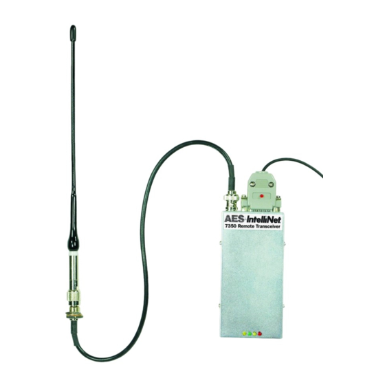
Page 7: Illustration
AES 7350 Integrated Transceiver Kit -- Installation and Operation Manual Illustration AES 7350 Integrated Transceiver Kit Reset Button - recessed 7350-10 Male BNC Antenna Assembly Connector Phone Line Input for Cut Detection Trbl – Antenna cut LED Indicators Label 26-Pin DB connector... -
Page 8: Installation And Operation
AES 7350 Integrated Transceiver Kit -- Installation and Operation Manual 2 Installation and Operation This section contains information on the installation and wiring of the 7350 Integrated Transceiver Kit. Overview The AES 7350 Integrated Transceiver Kit combines the electronics of an AES subscriber unit and a radio transceiver into one enclosure sized similar to a stand alone AES 7080 Transceiver. - Page 9 AES 7350 Integrated Transceiver Kit -- Installation and Operation Manual Illustration Below Shows a Typical Installation Diagram 2 – Example Control Panel Installation 40-7350, Rev 2, 6/10/2021 AES Corporation...
-
Page 10: Wiring - General
AES 7350 Integrated Transceiver Kit -- Installation and Operation Manual Wiring - General Diagram 3 below shows details of the 7350-10 interface board which is provided to allow the ease of connections to the alarm panel. User wiring is terminated to the connectors on this board. -
Page 11: Wiring - Antenna Cut / Acknowledge Delay Output (J5)
If the radio channel is "quiet" for more than 4 minutes (as would be the case if the antenna was cut) the 7350 subscriber attempts to send a test message to another subscriber. If that message is not acknowledged within the programmed acknowledgment delay period (default is 2 minutes), a fault condition exists. -
Page 12: Wiring - Zone Inputs
See Central Station Compatibility notes. Notes on Central Receiver Compatibility The 7350 Subscriber Unit is fully compatible with AES Version 1.70 Central Receiver and up. A receiver manufactured or updated after July 1997 usually complies with this requirement. Contact AES if your receiver is pre-1.70 for upgrade options. - Page 13 AES 7350 Integrated Transceiver Kit -- Installation and Operation Manual Zone Wiring diagrams Diagram 5 – Wiring Examples IMPORTANT: FOR ALARM PANELS WITH VOLTAGE OUTPUTS: Resistors must be added so that the voltage at the subscriber unit input terminals DOES NOT EXCEED 6V. Excess voltage on any zone may cause false alarms in all zones.
-
Page 14: Power Up
With the external power supply de-powered, connect the output of a 12VDC to the terminals labeled +12 and –12 of the 7350-10 board. Connect programmer to J3 on the 7350-10 interface board. (See Diagram 3) Connect the battery leads to the battery terminals while observing polarity. -
Page 15: Status (Led) Indicators
AES 7350 Integrated Transceiver Kit -- Installation and Operation Manual Status (LED) Indicators There are 4 LED indicators protruding through the cover of the 7350 transceiver. The function of each is described below. STATUS INDICATORS: LED's on cover at opposite end from RF. -
Page 16: Programming
AES 7350 Integrated Transceiver Kit -- Installation and Operation Manual 3 Programming Programming is accomplished by attaching a compatible programmer to the J3 connector of the 7350-10 Interface board. Following are programming instructions using the AES 7041 Hand Held Programmer. Software at the AES central receiver can also be used to program some of the functions listed in this section. -
Page 17: Set Packet "Time-To-Live" Function
AES 7350 Integrated Transceiver Kit -- Installation and Operation Manual The Reporting Delay sets the rate at which a subscriber’s own signals are transmitted. The default value is 10 seconds; transmissions are sent at least 10 seconds apart (this helps to meter traffic on the system). The range is 0 (no delay, not recommended) to 330 seconds. - Page 18 AES 7350 Integrated Transceiver Kit -- Installation and Operation Manual To start, press programmer key (F2). The following message appears: PACKET TIME TO LIVE CHECK IN----OLD:NEW [0-24] (HH = existing data) ENTER HRS----HH:.. Press <ENTER> then the following appears: [0-59] (MM = existing data) ENTER MINS---MM:..
-
Page 19: Zone Programming
AES 7350 Integrated Transceiver Kit -- Installation and Operation Manual Zone Programming Factory default zone programming is set to EOL Supervision (S) without restore (X). If this is satisfactory skip to the next section. To start, press programmer keys (CTRL + F3) (hold CTRL and then press F3). -
Page 20: Set Modes - Line Cut Monitor And Enable Repeating
The 7350 can monitor an attached phone line for line cut. Connect the phone line to terminals at J4 (see diagram 3). The 7350 senses the voltage on the line. If the line voltage drops below 3V for at least 2 minutes, the 7350 transmits a “Trouble” on “Zone 5”... -
Page 21: Reset Ram
AES 7350 Integrated Transceiver Kit -- Installation and Operation Manual Reset RAM Use the Reset RAM function to return the 7350 to the factory default settings. All parameters except the Unit ID (also referred to as the account number or code) and Cipher code (also known as the system ID) are returned to default values. -
Page 22: Local Status Check
AES 7350 Integrated Transceiver Kit -- Installation and Operation Manual Local Status Check This function performs a quick diagnostic check at any time. Use the handheld programmer: press SHIFT+F4. The following message appears: SUB [rev#] 7350 ID#:[NNNN] (C)YYYY AES RT1:NNNN LEVEL:... -
Page 23: Programming The Subscriber Unit From A Pc
In place of a handheld terminal, a cable adapter kit #7043 may be ordered from AES to link the 7350 to your computer serial port. Use a terminal program like Hyper- Terminal or Telix to send keystrokes to and display output from the programming port of the 7350. -
Page 24: Maintenance, Compliance, Warranty And Repair
Observe the RX light on the 7350. If it is on steady or most of the time you may be receiving some RF or electrical interference. Try different locations for the antenna or use a remote long range RF antenna. -
Page 25: Regulatory Compliance
AES 7350 Integrated Transceiver Kit -- Installation and Operation Manual Regulatory Compliance The AES Model 7350 product has not been submitted for either Canadian or USA identification or compliance and so is not intended for use in the USA and Canada. -
Page 26: Warranty And Service Procedure
Items should be shipped freight prepaid c/o Repair Services, AES Corp, 285 Newbury AES Corporation (“AES”) warrants to the original purchaser that each AES Subscriber Product will be free from Street, Peabody, Massachusetts 01960 USA. Authorized repair service is furnished only by AES defects in material and workmanship for three (3) years from date of purchase and all other products purchased from AES including central station receivers and accessories will be warranted for one (1) year from the date of purchase.
Need help?
Do you have a question about the 7350 and is the answer not in the manual?
Questions and answers