Table of Contents
Advertisement
Quick Links
Support / Wiki:
SiRad Easy® / Simple®
User Guide
Status:
Date:
Release
27-Apr-2021
Version:
Product number:
-
2.4
Document:
Annex to VAˍU03ˍ01
Author:
Silicon Radar GmbH
Package:
-
Anlage 8ˍTemplateˍDatenblattˍRevE
Filename:
UserGuideˍSiRadˍEasyˍSimple
Marking:
-
Date: 19-May-2020
Silicon Radar GmbH
Im Technologiepark 1
15236 Frankfurt (Oder)
Germany
fon +49 (0) 335 228 80 30
fax +49 (0) 335 557 10 50
https://www.siliconradar.com
https://wiki.siliconradar.com
Page:
1 of 13
Rev D
Advertisement
Table of Contents

Related Manuals for Silicon Radar SiRad Easy

Summary of Contents for Silicon Radar SiRad Easy
- Page 1 Silicon Radar GmbH Im Technologiepark 1 15236 Frankfurt (Oder) Germany fon +49 (0) 335 228 80 30 fax +49 (0) 335 557 10 50 https://www.siliconradar.com https://wiki.siliconradar.com SiRad Easy® / Simple® User Guide Status: Date: Author: Filename: Release 27-Apr-2021 Silicon Radar GmbH UserGuideˍSiRadˍEasyˍSimple...
-
Page 2: Table Of Contents
Table of Contents Overview ..........................4 Features ..............................4 Application ............................... 5 Hardware Setup SiRad Easy® ....................5 Changing the Radar Front End ......................... 5 Data Connection Mode - External Header (J1) ..................6 2.2.1 Serial/USB Data Connection ........................6 2.2.2... - Page 3 SiRad Easy® / SiRad Simple® User Guide Version 2.4 27-Apr-2021 List of Figures Figure 1 SiRad Easy® (left) and SiRad Simple® (right) .................... 4 Figure 2 24 GHz configuration ..........................5 Figure 3 122 GHz configuration with lens assembled .................... 5 Figure 4 External header (J1) pinout ........................
-
Page 4: Overview
FMCW or CW radar principles (frequency modulated continuous wave or continuous wave principles). SiRad Easy® consists of an evaluation baseband board and a microcontroller board. The baseband can hold exchangeable radar front ends (24 GHz to 300 GHz), all stackable as shown in Figure 1 (left). SiRad Simple®... -
Page 5: 1.2 Application
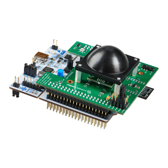
Hardware Setup SiRad Easy® Changing the Radar Front End Figure 2 and Figure 3 show the SiRad Easy® with 24 GHz and 122 GHz radar front end boards mounted. Follow the instructions below for changing the front end board. Figure 2... -
Page 6: Data Connection Mode - External Header (J1)
Figure 5 Hardware configuration for Serial/USB connection SiRad Easy® can now be connected to a PC using a USB cable. We recommend using an active USB Hub between the PC and SiRad Easy®. Alternatively, the board can be powered by a 5V DC power supply via the external header (pins 5V and any of the four GD pins). -
Page 7: Firmware Update
2.3.2 WiFi Module Connect the SiRad Easy® using a Serial/USB (FTDI) cable or Serial/USB adapter as shown in Figure 7 using the external header (J1). Please read Section 2.2 about the external header connection. Then connect cable TX to WR (WiFi RX) and cable RX to WT (WiFi TX). -
Page 8: Usb Controller Firmware
Download and extract the ST-LINK firmware update tool. Go into the AllPlatforms folder and start the .jar file. Connect the SiRad Easy®, click Refresh device list and then Open in update mode to see the current USB controller firmware. Click Upgrade to flash it to the latest version. -
Page 9: Wireless Data Connection
Evaluation Kit SiRad Easy® / SiRad Simple® User Guide Version 2.4 27-Apr-2021 Figure 10 UART pinout on J1 (left) and Serial/USB (FTDI) cable connection at J1 (right) The Serial/USB (FTDI) cable’s VCC is connected to +5V, the cable’s GND to any GD pin (there are four), the cable’s RX to the TX line of the microcontroller (MT) and the cable’s TX to the RX line of the microcontroller (MR). -
Page 10: Wifi Module
Evaluation Kit SiRad Easy® / SiRad Simple® User Guide Version 2.4 27-Apr-2021 Download the stm32flash tool. Copy the desired firmware into a folder together with the stm32flash tool. Edit the batch file stm32flash.bat and replace the COM port with the COM port of your Serial/USB (FTDI) cable or Serial/USB adapter and the firmware name with the desired firmware, for example: stm32flash.exe -b 115200 -w <date>_SiRad_Simple_L8_<version>.bin -v -g 0x0 COMx... -
Page 11: Mounting A Lens (Optional)
SER1 – Serial/UART is available on the external header (J1), lines MR and MT. SER2 – Serial/USB is available on the USB port (only on SiRad Easy®). You can connect to both SER1 and/or SER2 using a terminal program such as Realterm [7], PuTTY [8] or third- party software instead of the COM2WebSocket Tool / WebGUI [5]. -
Page 12: References
Evaluation Kit SiRad Easy® / SiRad Simple® User Guide Version 2.4 27-Apr-2021 References https://siliconradar.com/products/ https://siliconradar.com/datasheets/Protocol_Description_Easy_Simple.html https://siliconradar.com/datasheets/Datasheet_Collimator_Lens.html https://login.siliconradar.com/ https://siliconradar.com/datasheets/User_Guide_WebGUI_Easy_Simple.html https://siliconradar.com/wiki/Firmware_Update https://realterm.sourceforge.io https://www.putty.org/ - 12 -... -
Page 13: Disclaimer
Silicon Radar GmbH 2021. The information contained herein is subject to change at any time without notice. Silicon Radar GmbH assumes no responsibility or liability for any loss, damage or defect of a product which is caused in whole or in part by...
Need help?
Do you have a question about the SiRad Easy and is the answer not in the manual?
Questions and answers