Table of Contents
Advertisement
Quick Links
Installation & Operation Manual
Merlin 2000X
Merlin 2000X
Installation & Operation Manual
Please read this manual carefully and retain for future use.
The Merlin 2000X is a gas proving and gas detection controller with ventilation interlocking and current
monitoring.
Information contained within this manual should be referenced for typical installation and operation only.
For specific requirements that may deviate from the information in this guide – contact your supplier.
Rev: 1
1
Advertisement
Table of Contents

Related Manuals for S&S Northern Merlin 2000X


Summary of Contents for S&S Northern Merlin 2000X
- Page 1 Installation & Operation Manual Please read this manual carefully and retain for future use. The Merlin 2000X is a gas proving and gas detection controller with ventilation interlocking and current monitoring. Information contained within this manual should be referenced for typical installation and operation only.
-
Page 2: Table Of Contents
Installation & Operation Manual Merlin 2000X Contents IMPORTANT WARNING STATEMENTS ............ 3 INSTALLATION ..................4 Planning ..........................4 Mounting ..........................4 Board Connections Diagram ..................... 5 Board Connections Overview ................... 6 Access Configuration Settings ..................8 Configuration Settings Explained ..................8 Factory Set Condition ...................... -
Page 3: Important Warning Statements
Installation & Operation Manual Merlin 2000X IMPORTANT WARNING STATEMENTS Please take the time to thoroughly read this user’s guide which should be retained for future reference. It is recommended that this device be commissioned upon installation. Do not apply lighter gas or other aerosols to external gas detectors or monitors – this can cause extreme damage to the gas sensing elements. -
Page 4: Installation
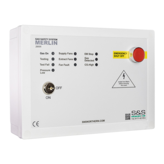
This panel can be used to carry out gas proving testing on pipe work to check if there is a gas appliance left open or potential gas leak. The Merlin 2000X is designed to give the user full control over incoming gas supply with the lockable main key-switch and touch sensors. The panel can monitor gas levels in the air by connecting carbon dioxide, natural gas, carbon monoxide and LPG sensors. -
Page 5: Board Connections Diagram
Installation & Operation Manual Merlin 2000X Board Connections Diagram WARNING! To avoid electrical shock you must always isolate the mains supply before opening the panel! Take care when making connections to high voltage connectors! Avoid running mains wiring across the circuit board! -
Page 6: Board Connections Overview
Installation & Operation Manual Merlin 2000X Board Connections Overview 1. POWER / LINE IN. 100-240Vac electrical power should be supplied to the [POWER / LINE IN] terminal and fused at 3A. On connecting the mains supply to the panel the power LED indicator will light up – this is located on the front cover (red dot of logo). - Page 7 Installation & Operation Manual Merlin 2000X 7. CURRENT MONITOR There are two terminals on the circuit board, one detailed as pictured [SUPPLY FAN LIVE] the other detailed [EXTRACT FAN LIVE]. The live feed from the fan controller should be connected to either the supply or extract side depending on which fan/s are being monitored.
-
Page 8: Access Configuration Settings
Installation & Operation Manual Merlin 2000X Access Configuration Settings On the front fascia circuit board you’ll find a [SETTINGS] dip-switch – when switched ON (before turning the panel on) via the key switch, the screen will display the settings menu – you can now configure your panel. -
Page 9: Factory Set Condition
Installation & Operation Manual Merlin 2000X If fans are calibrated, this will be set as ‘OK’. FANS CALIB. - OK See section: Fan Calibration to calibrate fans. Dropout threshold for Min and Max current values of both supply and - 10 extraction fans. -
Page 10: Fan Dropout Threshold Values
Installation & Operation Manual Merlin 2000X Fan Dropout Threshold Values When [FANS THRESHOLD] is selected in the settings menu, the user can adjust the minimum and maximum current values by 10, 20, 30 or 40%. Fans with a current between 0.1 to 0.2A we recommend a dropout threshold ≥ 30%. -
Page 11: Specification
Installation & Operation Manual Merlin 2000X Specification Model: 2000X Display 1.8” Screen TFT (located inside) Power Input Voltage 100-240Vac Gas Valve Output Voltage 100-240Vac BMS Max Output Single phase AC current monitor calibration range 0.1 – 18 Amps Single phase AC current monitor display... -
Page 12: Operation
Installation & Operation Manual Merlin 2000X OPERATION First Power Up 1. Supply mains power, the red LED on the front of the panel will illuminate (dot on logo). 2. Turn fans on. 3. Turn the key switch to on position. -
Page 13: Utility Touch Buttons / Led Indication Status
Installation & Operation Manual Merlin 2000X High If the concentration of CO2 in the air is at alarm level (relevant detector required), the LED will illuminate and the gas supply is isolated. Fire Alarm If the fire panel connected detects a fire the LED will illuminate and the gas is isolated. -
Page 14: System Diagnostics
Installation & Operation Manual Merlin 2000X System Diagnostics WARNING! Contact with mains electrical power can be fatal! The panel can display fan current (Amps) and gas pressure (mbar). To view these diagnostics, carefully remove the front fascia of the panel, to activate screen diagnostics, press either the [OK], [UP] or [DOWN] button. - Page 15 Installation & Operation Manual Merlin 2000X ENGINEERING NOTES - Blank Rev: 1...
-
Page 16: Installation Details
Installation & Operation Manual Merlin 2000X Installation Details Please pass this manual to the system owner or system user. Date of Installation: Installation Location: Organisation: Stamp/ Signature of the installer: S&S Northern Head Office Tel: +44(0) 1257 470 983 Fax: +44(0) 1257 471 937 www.snsnorthern.com...
Need help?
Do you have a question about the Merlin 2000X and is the answer not in the manual?
Questions and answers