
Summary of Contents for Bombardier-Rotax ROTAX FLYDAT
- Page 1 FLYDAT OPERATOR'S MANUAL ROTAX-BOMBARDIER ® Flydat operator's manual Non TSO approved...
-
Page 2: Table Of Contents
Content CONTENT OF Section 1 Operator's manual page ii Introduction............. Section 2 page 1 ® Description.............. Section 3 page 2 Description of design..........Section 4 page 3 Possible configuration..........Section 11 page 4 Liquid cooled 2-stroke..........page 19 Initial start-up............page 5 Air cooled 2-stroke.......... -
Page 3: Introduction
Operator's Manual carefully, as it will acquaint you with the basic knowledge of technical data, installation and the safe handling of the BOMBARDIER-ROTAX G.m.b.H & Co.Kg Aircraft engines division If you do not understand anything in this manual or in case... -
Page 4: Description
Description INTRODUCTION Description Section has not undergone any safety and durability ® examination to the Standards of Civil Aviation, but it does incorporate the latest technical development and has been thoroughly tested. Despite the being a precise instrument, false indication or misinterpreting of data could occur. By utilizing the FLYdat , the user acknowledges... -
Page 5: Description Of Design
Description of design INTRODUCTION Description Section represents an instrument specially developed ® for ROTAX Aircraft engines for the indication and acquisition of engine operating data readily accessible for the pilot. is furnished with 8 sensor input ports, which can be occupied variably according to the engine type. The operating data is being permanently compared with the The separately picked up readings are issued in accordance specific... -
Page 6: Possible Configuration
Possible configuration INTRODUCTION Configuration Section FLYdat is supplied by Rotax with an undefined ® configuration. With the standard configuration, all trigger levels for warning and alarm system are set to the maximum of the measuring range , i.e. no checks for exceeding the warning limits. FLYdat can be coordinated by the authorized... -
Page 7: Liquid Cooled 2-Stroke
Liquid cooled 2-stroke CONFIGURATION Display and connection FLYdat is always delivered with the front plate for 4-stroke engines but without a defined configuration. By programming the FLYdat , it will be adapted to the ® respective engine type. 2-stroke liquid cooled engine configuration: Wiring diagram: EGT/PTO EGT/PTO... -
Page 8: Air Cooled 2-Stroke
Air cooled 2-stroke CONFIGURATION Display and connection FLYdat is always delivered with the front plate for 4-stroke engines but without a defined configuration. By programming the FLYdat , it will be adapted to the ® respective engine type. 2-stroke air cooled engine configuration: Wiring diagram: EGT/PTO CHT/PTO... -
Page 9: Liquid Cooled 4-Stroke
Liquid cooled 4-stroke CONFIGURATION Display and connection FLYdat is always delivered with the front plate for 4-stroke engines but without a defined configuration. By programming the FLYdat , it will be adapted to the ® respective engine type. 4-stroke liquid cooled engine configuration: Wiring diagram: EGT/PTO OIL TEMP... -
Page 10: Possible Connection
Possible connection CONFIGURATION Display and connection Section FLYdat has another input that should be ® used for programming, communication with other instruments via the iFamily® bus and also for the external switch and signalization unit. Alarm lamp and external Push-Button: Communication with the PC: When the Push Button on the front panel is out of hand reach, connect the external Push Button into the connector. -
Page 11: Technical Data
Technical Data TECHNICAL DATA Technical data Section For correct working of the , always keep the technical parameters as specified below. Any use of the ® beyond the range of the technical parameters may cause a damage, to which the guarantee will not be related. If you use the Flydat above the temperature limits, the warning Sensors inputs: message "OVER RANGE"... -
Page 12: Warning And Alarm 447, 503, 582Ul
Warning and Alarm LIMITS Warning and Alarm Section If the FLYdat has been configured by a distributor, ® the following limits are stored. NOTE: Please, pay attention to the limits as specified in the Operator's manual for the engine. Do not run the engine above these limits. Engine type 582 UL DCDI: Engine type 447 and 503UL: Display... - Page 13 Warning and Alarm LIMITS Warning and Alarm If the FLYdat has been configured by a distributor, ® the following limits are stored. NOTE: Please, pay attention to the limits as specified in the Operator's manual for the engine. Do not run the engine above these limits Engine type 912 UL DCDI: Engine type 618 UL: Display...
- Page 14 Warning and Alarm LIMITS Warning and Alarm If the FLYdat has been configured by a distributor, the following limits are stored. ® NOTE: Please, pay attention to the limits as specified in the Operator's manual for the engine. Do not run the engine above these limits. Engine type 912 ULS DCDI: Engine type 914 UL DCDI: Display...
-
Page 15: Installation
Installation GENERAL INFORMATIONS Installation Section Prior to the installation of the FLYdat look for a suitable ® location in the cockpit, taking the following into consideration: Protection against too high temperatures. NOTE: The unit operates flawless up to the max. operating Outline dimensions of the Flydat temperature of 70°C. -
Page 16: Sensors Kits
Sensors kits GENERAL INFORMATIONS Section Sensors kits 3 different sensor kits, specially assembled for every engine type, are offered from Bombardier-Rotax. ® Version LC (liquid cooled 2-stroke engines) Version AC (air cooled 2-stroke engines) 2 sensors for exhaust gas temperature (EGT) -
Page 17: Installation Of The Sensors
NiCrNi thermocouple cables are available in a specialist store must be greased with Loctite ANTI-SEIZE to ensure or from your local Bombardier-Rotax dealer. a trouble-free removal (see the tightening torque chart). All other sensors can be extended with a suitable stranded copper Shortcomings in these points can result in false readings, wire. -
Page 18: Installation Of The Sensors
Installation of the sensors GENERAL INFORMATIONS Sensors Installation These sensors are offered by Bombardier-Rotax: ® CHT sensor EGT sensor Tightening torques: Sensor Torque Tightening EGT sensor 20Nm 177in.lb. LOCTITE Anti Seize Oil pressure pick-up 15Nm 133in.lb. LOCTITE 603 CHT sensor ( 912, 912S / 914 ) 15Nm 133in.lb. - Page 19 Installation of the sensors GENERAL INFORMATIONS Sensors Installation Installation plan for the individual sensor kits ® liquid cooled 2-stroke engines (Illustration shows the engine type 582 UL) Air cooled 2-stroke engines (Illustration shows the engine type 503 UL) Index Description Index Description Sensor at spark plug seat (CHT)
- Page 20 Installation of the sensors GENERAL INFORMATIONS Sensors Installation Installation plan for the individual sensor kits ® liquid cooled 4-stroke engines (Illustration shows the engine type 912 UL) Index Description Oil pressure pick-up Oil temperature sensor CHT sensor page 17 Flydat Operator's manual Rev.
-
Page 21: Initial Start-Up
Operation Section Initial Start-up ® Prior to putting the into operation, make sure that all the sensor lines and the supply cable are connected correctly. Reaction at start Consult the wiring diagram and the chapter about the electric connections for the particular type of engine. After connecting the unit on power, it will perform an autotest. -
Page 22: Delete Service Message
Operation Message and light Section Delete "SERVICE" message ® To delete this message, turn the instrument off. Then, while Signalization unit keeping the pressed button on the panel or the external button connected to the pin 7 of the connector on the backside The signalling control lamp on the panel of the instrument of the instrument, turn the instrument on. -
Page 23: Possible Display
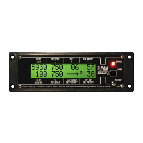
Possible display Possible display Section Indication of engine speed ® The r.p.m. reading is in 4 digits and shows on the display Temperature indication from 300 r.p.m. onwards. Recording of the speed down to (Exhaust gas, cylinder head, oil and air temperature) 1000 r.p.m. -
Page 24: Flydat Status
Flydat status Flydat status Section Flydat can be programmed by an authorized ® dealer for different Warning and Alarm limits, depending on the engine type. Distinguish three ranges of the status: WARNING: Ignoring of the Warning and Alarm signal may cause injures or endanger the life green range (standard operation) of the operator or the third party. -
Page 25: Data Recording In Operation
Data recording in operation Data recording Section FLYdat stores the current measured values (the values ® you can see on the display of the instrument) in the interval of 5 seconds. The values are stored in the ScheckK® memory, which has: Signalization unit 4-hour rolling memory, where the measured values are... -
Page 26: Data Downloading
Data downloading Data downloading Section is also delivered with the connecting cable for ® connecting the instrument with your PC. The communication is via the serial cable RS-232, which is a standard part of desktop computers. In portable PCs, there is usually a USB port and, Flydat down loader therefore, it is necessary to purchase a USB/RS-232 reduction, which is available in every shop with PC accessories. -
Page 27: Firmware Update
Firmware Update Firmware update Section offers the possibility of firmware update by ® means of a PC and the programme, which is delivered on a disc or CD and which is a part of the delivery. To undertake the firmware update, first, download the latest Since the firmware for your is to be improved and version of the file with the "tls"... -
Page 28: Ifamily® Bus
iFamily® bus iFamily bus Section offers a wide range of possibilities by ® connecting with other instruments by means of the iFamily bus. One of these possibilities is e.g. connecting with the wireless communication module GPRS for data transfer from the iFamily®... -
Page 29: Message And Reports Of Errors
Messages and Report Errors of Errors Section ® Warning message "COLD ENGINE" If the oil temperature in a 4-stroke engine does not reach the operating value and, at the same time, the rotation speed has Report of Errors exceeded the set value, the warning message "COLD ENGINE" will show on the display and the lamp control on the panel of Test of memories the instrument will light up red. - Page 30 BOMBARDIER-ROTAX G.m.b.H & Co.Kg Aircraft engines division A-4623, Gunskirchen, Austria Web side address: http://www.rotax-aircraft-engines.com ROTAX-BOMBARDIER ® Printed in Czech Republic Created by TL elektronic, Czech Republic...
Need help?
Do you have a question about the ROTAX FLYDAT and is the answer not in the manual?
Questions and answers