Advertisement
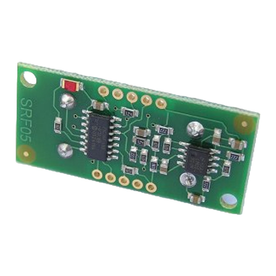
SRF05 Technical Documentation
Introduction
The SRF05 is an evolutionary step from the SRF04, and has been designed to increase flexibility, increase range, and to
reduce costs still further. As such, the SRF05 is fully compatible with the SRF04. Range is increased from 3 meters to 4
meters. A new operating mode (tying the mode pin to ground) allows the SRF05 to use a single pin for both trigger and
echo, thereby saving valuable pins on your controller. When the mode pin is left unconnected, the SRF05 operates with
separate trigger and echo pins, like the SRF04. The SRF05 includes a small delay before the echo pulse to give slower
controllers such as the Basic Stamp and Picaxe time to execute their pulse in commands.
Mode 1 - SRF04 compatible - Separate Trigger and Echo
This mode uses separate trigger and echo pins, and is the simplest mode to use. All code examples for the SRF04 will work
for the SRF05 in this mode. To use this mode, just leave the mode pin unconnected - the SRF05 has an internal pull up
resistor on this pin.
http://www.robot-electronics.co.uk/htm/srf05tech.htm (1 di 4)09/03/2007 15.41.31
SRF05 - Ultra-Sonic Ranger
Technical Specification
Advertisement
Table of Contents

Related Manuals for Futura SRF05

Summary of Contents for Futura SRF05
- Page 1 This mode uses separate trigger and echo pins, and is the simplest mode to use. All code examples for the SRF04 will work for the SRF05 in this mode. To use this mode, just leave the mode pin unconnected - the SRF05 has an internal pull up resistor on this pin.
- Page 2 To use this mode, connect the mode pin to the 0v Ground pin. The echo signal will appear on the same pin as the trigger signal. The SRF05 will not raise the echo line until 700uS after the end of the trigger signal. You have that long to turn the trigger pin around and make it an input and to have your pulse measuring code ready.
- Page 3 The SRF05 Timing diagrams are shown above for each mode. You only need to supply a short 10uS pulse to the trigger input to start the ranging. The SRF05 will send out an 8 cycle burst of ultrasound at 40khz and raise its echo line high (or trigger line in mode 2).
- Page 4 SRF05 Technical Documentation that I'm aware of. The beam pattern of the SRF05 is conical with the width of the beam being a function of the surface area of the transducers and is fixed. The beam pattern of the transducers used on the SRF05, taken from the manufacturers data sheet, is shown below.
Need help?
Do you have a question about the SRF05 and is the answer not in the manual?
Questions and answers