Table of Contents
Advertisement
Quick Links
User's Manual Version 1.0
The information presented in this publication has been made
carefully for reliability; however, no responsibility is assumed
for inaccuracies. Specifications are subject to change without
notice.
IBM, PC/AT, and PC/XT are trademarks of International Busi-
ness Machines Corporation.
Pentium is a trademark of Intel Corporation
AWARD is a registered trademark of Phoenix Sofftware Inc.
MS-DOS and WINDOWS NT are registered trademarks of
Microsoft Corporation.
Trademarks and/or registered trademarks are the
properties of their respective owners.
Advertisement
Table of Contents

Related Manuals for Acorp 6BX83


Summary of Contents for Acorp 6BX83
- Page 1 User's Manual Version 1.0 The information presented in this publication has been made carefully for reliability; however, no responsibility is assumed for inaccuracies. Specifications are subject to change without notice. IBM, PC/AT, and PC/XT are trademarks of International Busi- ness Machines Corporation. Pentium is a trademark of Intel Corporation AWARD is a registered trademark of Phoenix Sofftware Inc.
-
Page 2: Table Of Contents
Clearance Requirements ......16 Fan Exhaust ..........16 External Connectors ........17 Chapter4 Audio Installation........26 Note: If there is any change in the content please refer to our website.Regarding the BIOS setting & Driver installation,refer the web site please.(www. acorp.com.tw) -
Page 3: Chapter 1 Introduction
Chapter 1 Introduction How This Manual is Organized This manual is divided into the following sections: Chapter 1 Introduction : Manual information and checklist. Chapter 2 Features : Information and Specifications con- cerning this mainboard. Chapter 3 Installation : Instructions on setting up the board. Chapter 4 Audio Installation Chapter 1 Introduction / 1... -
Page 4: Package Checklist
Package Checklist Please check that your package is complete . If you discover any item damaged or missing , please contact with your retailer immediately. The 6BX83 mainboard. 1 x IDE ribbon cable. 1 x floppy ribbon cable. 6BX83 support software: CD driver and utilites. -
Page 5: Chapter 2 Features
Chapter 2 Features Features of the 6BX83 Mainboard The 6BX83 is designed for the PC user's who want many new key features processed by the fastest CPU in a economic package. This mainboard : New general CPU support : Socket 370 for Intel PPGA/FC-PGA PII/PIII processor. - Page 6 Chipset : Intel 82443BX chips with I/O subsystems. Biggest memory capacity : 6BX83 is equipped with four DIMM socket to support (16MB, 32MB, 64MB, 128MB.256MB) 168 pin 3.3v SDRAM SPD(Special Presence Detect).Maximum memory up to 1024MB. AGP for fast VGA solution : AGP (Accelerator Graphic Port) will enhance &...
- Page 7 CPU built-in Level 2 Cache : 128/256KB Pipeline Burst Level 2 cache in the PII/III CPU processors. WOL (Wake On LAN) : Supports system power up from LAN ring up . IrDA Port : Support this serial fast communication up to 115.2Kbps. Support Ring on by modem/Alarm on : Support System power up from Modem ring up or timer of System.
-
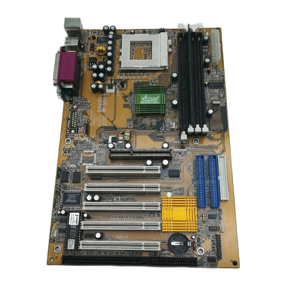
Page 8: The Mainboard Layout
The 6BX83 Mainboard layout down : :Mouse CO M1 Printer C O M 2 82443BX MIDI/ GAME/ AUDIO ISA SLOT1 6 / Chapter 2 Features... -
Page 9: Chapter 3 Installation
Chapter 3 Installation Jumper Jumper Refer to page - Real time Clock RTC clean FAN1 - FAN CONN. for CPU FAN2 - FAN CONN. for AGP FAN3 - FAN CONN. for MB - LAN Card Wake Up JP6,JP7 - CPU Type Selection J6,JP1 - Onboard Sound Function Chapter3 Installation / 7... - Page 10 Expansion Slot Which page 168 pin DIMM Socket Socket 370 AGP (Accelerator Graphic port) SLOT PCI SLOT 1,2,3 -32bits PCI SLOT ISA SLOT1 - 16bits ISA SLOT Connectors Refer to page KB1(UP) - PS/2 Mouse port. KB1(DP) - PS/2 Keyboard port - USB1,2 Port COM1 - COM 1 serial port...
-
Page 11: System Installation Setups
System Installation Setup Before using your computer, you must finish the following steps: 1. Set jumpers on mainboard 2. Install SDRAM module. 3. Install the Processor. 4. Connect Ribbon Cables, Cabinet Wires, and Power supply. 5. Install Add on Cards. 6. -
Page 12: Jumper Settings
Jumper Settings Jumpers Several hardware setting are made through the use of jumper caps to connect jumper pins (Jxx) on the mainboard. See " Map of the mainboard" for locations of jumpers. The jumper settings will be described numerically such as [----], [1- 2], [2-3] for no connection, connect pins 1 &... - Page 13 Real Time Clock (RTC) RAM - JP5 : The CMOS RAM is powered by the onboard button cell battery. To clear the RTC data: (1)Turn off your computer, (2) Move this jumper to "3-4Pin Clear Data", (3) Move the jumper back to "Default", (4) Turn on your computer, (5) Hold down <Delete >...
-
Page 14: System Memory (Dimm Modules)
System Memory ( DIMM Module) This 6BX83 main board supports four 168 pins DIMM of 16 MB, 32 MB, 64 MB, 128 MB ,256MB to form a memory size between 16MB to 256MB. The DRAM can be either 45ns,50ns,or 60ns 3.3v SDRAM,and 3.3v Enhanced Data Output (EDO) RAM. -
Page 15: Dimm Memory Installation
DIMM Memory Installation Insert the module (s) as shown. Because the number pins are differ- ent on either side of the breaks,the module will only fit in the orienta- tion as shown. SDRAM DIMM modules have different pin contacts on each side and therefore have a higher pin density. down : :Mouse CO M1... - Page 16 The Dual Inline Memory Module (DIMM) memory module must be 3.3v Extended Data Output (EDO) DRAM or SDRAM. You can identify the type of DIMM module by the illustration below: Unbuffered 5.0V Reserved Buffered 3.3V Voltage Key Position DRAM Key Position 168 Pin DRAM DIMM Notch Key Definitions The notch on the DIMM module will shift between left, center, or right to identify the type and also to prevent the wrong type to be...
-
Page 17: Cpu Installation
CPU Installation The motherboard provides a ZIF socket 370. The CPU that came with the motherboard should have a fan attached to it to prevent overheating . If this is not the case then purchase a fan before you turn on your system. To install a CPU , first turn off your system and remove its cover. -
Page 18: Clearance Requirements
Selecting the CPU Frequency CPU voltage auto-detection and allow user to set CPU frequency through BIOS setup, no jumper or switch is needed. The correct CPU information is saved into EPROM, with these technologies, the disadvantages of Pentium base jumper-less design are eliminated. There will be no worry of wrong CPU voltage detection and no need to re-open the housing if CMOS battery loss. -
Page 19: External Connectors
EXTERNAL CONNECTORS Both Ribbon cable and Connectors on board are with direction signs to avoid that user insert wrong directions. On other hand, the ribbon cables should always be connected with the red stripe on the pin 1 of side of the connector. MIDI/(GAME) Port MIDI/(GAME) Port Parallel (Printer) Port... - Page 20 1. PS/2 Keyboard port This connection is for a standard keyboard using an PS/2 plug (mini DIN) . This connector will not allow standard at AT size (large DIN) keyboard plugs. You may use a DIN to mini DIN adapter on standard AT keyboards. 2.
- Page 21 7. FAN1 , FAN2 , FAN3 CPU Cooling Fan (FAN/PWR) These connectors support cooling fans of 500mAmp (6Watt) or less. Orientate the fans so that the heatsink fins allow airflow to go across the onboard heat sink(s) instead of the expansion slots. Depending on the fan manufacturer, the wiring and plug may be different.
- Page 22 8. Primary / Secondary IDE connectors (Two 40-pin Blocks) These connectors support the provided IDE hard disk ribbon cable. After connecting the single end to the board, connect the two plugs at the other end to your hard disk no space(s) . If you install two hard disks, you must configure the second drive to Slave mode by setting its jumper settings.
- Page 23 9. IrDA / Fast IR-Compliant infrared module connector - IR(J1) This connector supports the optional wireless transmitting and receiving infrared module. This module mounts to a small open- ing on system cases that support this feature. You must also configure the setting through UART2 Use Infrared” in Chipset Feature Setup to select whether UART2 is directed for use with COM2 or IrDA.
- Page 24 10.J5 J5 PANEL Connector PW_LED PW_BN HD_LED SMI LED SPEAK a. IDE activity LED (HD-LED) This connector supplies power to the cabinet’s IDE activity LED. Read and write activity by devices connected to the Primary or Secondary IDE connectors will cause the LED to light up. b.
- Page 25 e. Speaker Connector (SPEAKER) This 4-pin connector connects to the case-mounted speaker. f. ATX Power Switch (PW_BN) The system power is controlled by a momentary switch con- nected to this lead. Pushing the button once will switch the sys- tem ON. The system power LED lights when the system's power is on 11.
- Page 26 12. CD Audio Connector- CD_IN1/CD_IN2 The 4-pin connectors enable the system to receive the audio output from the CD-ROM. CD_IN1 Description down : CD-R :Mouse CD-L CO M 1 CD_IN2 Description CD-R Printer C O M 2 82443BX CD-L MIDI/ GAME/ AUDIO Wake-On-LAN Connector...
- Page 27 14.CPU Type Selection -JP6,JP7 Current PCI bus in limited to 33MHz, socket370 Celeron processors limited to 66MHz, and SDRAM limited to the DIMM type 66/100MHz. Other settings are for experienced users only. down : :Mouse CO M1 Printer C O M 2 82443BX MIDI/ GAME/...
-
Page 28: Chapter4 Audio Installation
Chapter 4 Audio Installation Audio Rack Introduction The Audio Rack32 enables you to take advantage of your computer's audio capabilities with all of the controls conveniently in one compact space. You can play audio CDs, wave files ( in .wav and .aud formats), and MIDI files (in .mid and .rmi formats). - Page 29 The AudioRack32 has six main parts: Command Center- customizes the appearance of the AudioRack32. Audio Mixer - Controls the volume and balance of the AudioRack32 devices. Digital Audio Player- plays and records files in the .wav format. MIDI Player - enables you to play MIDI files. Compact Disk Player - enables you to play audio CDs on a CD- ROM.
- Page 30 The Command Center Introduction The command center controls the parts of the AudioRack32 that are displayed. You can display or hide any part of the AudioRack32 you choose, customizing its appearance to suit your needs or desires. It also displays information on the status of the different audio components.
- Page 31 The Audio Mixer Introduction The Audio Mixer has two modes : playback mode and record mode. You can use these two modes to fully control the audio soources you are listening to or recording, how loud each of those sources are and how they are balanced.
- Page 32 The Digital Audio Player Introduction The digital audio player enables you to play, record, and compress sound as .wave files. In addition, you can play audio files. The wave files use PCM, which is the Windows' audio file format. The .aud format uses ESPCM compression to produce an audio file.
- Page 33 The MIDI Player has an indicator to show when you are listening to ESFM. When the EXFM light to the left of the playlist button is lit, the MIDI Player is using ESFM synthesis. ESFM performs superior- quality music synthesis compared to that of traditional FM, producing richer timbre and greater depth of instrument voices.
- Page 34 The Audio Recorder The audio recorder enables you to record, compress, store, and play back voice, music, and other sound. It provides settings for sound attributes such as mono/stereo, compression level, and sampling rate, You can use it to embed sound objects in documents created in appli- cations that support object linking and embedding (OLE).
- Page 35 Using AudioRack CD player as Default CD Player During installation, you will be asked if you want to use AudioRack CD player as the default CD player. Normally Windows 95 CD player is the default and will automatically run when as audio CD is inserted into the CD-ROM.
- Page 36 Guarantee Sheet/Technical Fault Report M/B Model No.: Vender Serial No. Date of Purchasing: Hardware Configuration Used : Video Card Hard Drive Other Card Diagnostic Software Used : Fault Description : Technical Support : WWW : www.acorp.com.tw fae@acorp.com.tw 34 / Chapter 4 Audio Installation...
Need help?
Do you have a question about the 6BX83 and is the answer not in the manual?
Questions and answers