Table of Contents
Advertisement
Advertisement
Table of Contents

Related Manuals for AfiMilk AfiAct II

Summary of Contents for AfiMilk AfiAct II
- Page 1 s Heat Detection TieStall™– Test Group Guide...
- Page 2 ...
- Page 3 Preface Preface AfiAct II™ Installation Product: Reader 2.0 Manual P/N 9440311 Version 2.7 Date Completed – June 2016 Afimilk Ltd., Kibbutz Afikim, 15148 Israel Tel: 972‐4‐6754812 | Fax: 972‐4‐6751862 market@afimilk.co.il | www.afimilk.com Federal Communications Commission, USA Conformité Européenne (European Conformity) Standards Institute of Israel AfiAct II™ Installation Manual June 2016 Page i...
- Page 4 Preface Preface Preface Material About this Manual and Scope This manual describes the installation of AfiAct II, either as a standalone system or as part of the larger Afimilk system. For a description of the features and usage of the AfiAct II system, refer to AfiAct II UM. Intended Users This manual is intended forAfimilk authorized technicians, experienced in installing electrical systems in non‐protected environments, for dealers‐technicians and farm technicians. Contacting Technical Support HelpDesk Afimilk technical support contact information: email: support@afimilk.co.il Tel: +972‐4‐675‐4824. AfiAct II™ Installation Manual June 2016 Page ii...
- Page 5 Reorient or relocate the receiving antenna. Increase the separation between the equipment and receiver. Connect the equipment into an outlet on a circuit different from that to which the receiver is connected. Consult the dealer or an experienced radio/TV technician for help. Changes or modifications to this equipment not expressly approved by the party responsible for compliance (Afimilk Ltd.) could void the user’s authority to operate the equipment. Ensure taking all precautions when working with the high voltage components.To comply with FCC RF exposure compliance requirements, the antenna used for this transmitter must be installed to provide a separation distance of at least 20 cm from all persons and must not be co‐located or operating in conjunction with any other antenna or transmitter. AfiAct II™ Installation Manual June 2016 Page iii...
- Page 6 Preface Preface Legal Notice Copyright Copyright © 2016 Afimilk Ltd., All Rights Reserved Disclaimer This document contains proprietary information of Afimilk Ltd. and may not be reproduced in any form without the prior written consent of Afimilk Ltd. No part of this document may be reproduced, translated, stored in a retrieval system or transmitted in any form and by any means, electronic, mechanical, photographic, photocopying, recording, or otherwise, without the prior written permission of Afimilk Ltd. Information provided in this document is subject to change without notice and does not represent a commitment on the part of Afimilk Ltd. All products and company names are trademarks or registered trademarks of their respective holders. Software License Terms The software and the system design is the property of Afimilk Ltd. It is supplied to the user to be used solely for its stated purposes. It is strictly forbidden to make copies of the software or transfer it in any way, for any purpose, to any third party. In addition to application software specifically developed by Afimilk Ltd., the system makes use of certain third party utilities and system software. These are licensed for a single user. They must not be copied in any way, for any purpose, by the user, its employees, or anybody else. The license to use the software is granted to the user only for the specific system it is installed on by Afimilk Ltd., or its authorized distributors and representatives. The purchaser shall not modify the software in any way. It is strictly forbidden to usethis product for any purpose other than originally designated for or stipulated by Afimilk Ltd. AfiAct II™ Installation Manual June 2016 Page iv...
- Page 7 Preface Preface Conventions Important information is highlighted in a frame, as explained below: Actions requiring special attention to avoid serious bodily injury; For example, working with high voltage components Actions requiring special attention, to avoid possible damage to equipment or livestock Hints and recommendations for working efficiently Environment notice AfiAct II™ Installation Manual June 2016 Page v...
- Page 8 The installation must be performed in accordance with current norms and regulations as well as local and national rules. Before installing and operating any equipment, review the safety instructions for any hazards associated with installation and use of the device. Also, review standard and local practices for preventing accidents. The system and its components are powered by electricity from main power supply. This power supply is sufficient to cause serious personal injury or even death. Only a (local state) licensed electrician should install power cables and power supply units. Use only a correctly rated power cable that is certified, as appropriate, for the country of operation. The AfiAct II must be powered by an external isolating transformer (output 21.6 ‐ 27.5Vac, 75 VA maximum, certified as LPS according IEC 60950‐1 clause 2.5) with an accessible circuit breaker and double isolated from mains. Read this manual carefully. Proper handling of the equipment is the basis for correct functioning. Only technicians who are skilled and authorized by Afimilk, dealer technicianstogether with the farm staff may carry out installation of the equipment. The customer is fully responsible for any changes made, either in the system configuration or in the software application data, by the customer or by the customer’s agent. Afimilk will not be held responsible directly or indirectly for any damage caused to the customer and/or to a third party and/or to the animals, by an action and/or change and/or omission performed in the AfiAct II™ system, either by the customer or by the customer’s agent, directly and/or indirectly. AfiAct II™ Installation Manual June 2016 Page vi...
- Page 9 Preface Preface Afimilk recommends that the customer call for a full system inspection by a qualified technician authorized by Afimilk every six months. It is the responsibility of the operator to install, operate, and maintain the system in accordance with all applicable laws, codes and regulations. The equipment must be used only for the described purpose. This system has been checked for viruses prior to supply.If in the course of a service call, a virus is detected, removal of the virus, and any software or hardware repairs resulting from it, will be charged to the purchaser. The system and its components are powered by electricity from a main power supply. To avoid personal injury, danger of fire, and possible damage to equipment and materials, all work on electrical and electronic circuits should be done following these basic safety procedures: Power to all Afimilk devices must be supplied through an accessible, well‐marked circuit breaker (usually placed on the power transformer). Before conducting work on any Afimilk device, make sure power to devices is switched off at the circuit breaker (usually placed on the power transformer). Remove power from the circuit or equipment prior to working on it. Never assume the circuit is off; check it with a multimeter. In case of electrical fire, switch off the circuit and report it immediately to appropriate authority. Stay away from live circuits. Do not work on or make adjustments when the power switch is on. Never switch on equipment in the presence of water leakage. Work in clean, dry areas. Avoid working in damp or wet locations because this increases the chance of electrical shock. ...
- Page 10 Preface Preface List of Terms and Abbreviations Term/Abbreviation Description RPU Tag Reading/Programming Unit AfiAct II AfiFarm module for generating cow database and providing general fertility reports. DIM Days in Milk ID Identification PC Personal Computer PD Pregnancy Diagnosis RF Radio Frequency LR Long Range radio i.e. 916/868 MHz, communication between Reader and tags SR Short Range radio i.e. 200/80 KHz RT Real Time system RTMS Real Time Setup module RTG Real Time GUI module ‐ AfiControl RTC Real Time Station Controller module RPM Revolutions per Minute Opcode Operation Code AP WiFi Access Point (antenna) WLAN ...
- Page 11 Preface Preface Revision History Version Date Description 1.00 Oct 2013 Revision one. 1.2 Oct 2013 Add FCC Approvals 2.0 Feb 2014 Update WIFI spec 2.2 PC requirements 2.3.1 re‐locate RT quick‐start (after RT installation) 4.2 add tag‐activation runtine 6.1 Update tag management 6 correct troubleshooting flow for disconnection, 7.1 Update antenna names 1.3.1 update location of RID label 0, correct wifi setings 4.4, remove tag survey section (covered by other sections), add backup settupError! Reference source not found., add db backup and restore. 2.1 Mar 2014 Correct supported Windows version, section 2.4.1 2.2 ...
-
Page 12: Table Of Contents
Preface Preface Table of Contents Preface Material ............................ii Table of Contents ............................ x Introduction ..........................1 Principle of Operation ......................1 Supported Scenarios ......................2 AfiAct II Components ......................2 1.3.1 Reader Box Components ..................... 3 1.3.2 Tag Types ..........................4 AfiAct II Reader – Indicators and I/Os ................. 5 1.4.1 Front Panel ‐ LED Indications ....................5 1.4.2 Back Panel – Inputs and Outputs ..................6 1.4.3 Reader box ‐ Attributes Label .................... - Page 13 Preface Preface Connect the Reader to Power ................... 81 Handle AfiTag II ......................... 82 Test AfiAct II Tags’ Transmission ..................83 Perimeter Coverage Validation ..................85 Attach AfiAct II Tags ......................87 Replace and re‐use Tags ....................90 Store Tags ......................... 92 Fault Identification and Troubleshooting .................. 93 Reader Connection to AfiControl or Network Fault ............94 Tag Problems ........................95 Reader and Tag Communication Faults ................96 Reader’s Luci Cannot be Accessed ..................96 Back‐to‐Back Connection ....................97 Region Transmission Setup ....................
-
Page 14: Introduction
Introduction Chapter 1 Introduction AfiAct II is an estrus and fertility monitoring system that provides at a glance full picture of cows and heifers in estrus. The monitoring system provides thorough tracking of the fertility‐related data for the dairy farm herd. It can be implemented either as a standalone system or as part of a comprehensive Afimilk system. This is done by collecting cows’ physical behavior and aggregating them with events information to generate heat lists, fertility reports and fertility disorder alerts. 1.1 Principle of Operation The following diagram shows the data flow in the AfiAct II system. Figure 1: AfiAct II system data flow Wired/Wi‐Fi communication Long Range (LR) communication AfiAct II uses Long Range (LR) communication to collect data from cow tags (AfiTag II sensors) and transfers the information via a standard network (IP based Wi‐Fi or wired communication) to a PC based analysis. Tags are placed on the cows’ legs. The AfiTag II holds the unique ID of each cow, and records its number of steps, standing time, rest time and bout. The tags use LR (Long Range) RF (Radio Frequency) communication to send this data periodically (every pre‐defined time‐interval, default is 15 minutes) to an antenna located inside the AfiAct II Reader device (two antennas that provide optimal coverage). AfiAct II Reader collects data from the cows’ tags which are within its receiving range. The Reader uses either wired or Wi‐Fi communication to send the data to the PC for analysis (2 internal antennas are for Wi‐Fi, when used). The AfiAct II software, located on the PC, uses the collected activity data of each cow to calculate when the cow is in estrus and find the best time for breeding. The application generates reports and alerts the farmer. The communication used by the entire system complies with local regulations and safety tests, corresponding with the ‘home appliance’ category. ... -
Page 15: Supported Scenarios
PNs – see: AfiAct II The Reader is the 1.3.1 Reader 2.0 interface between (including the tags and the nounting AfiAct II Software. brackets) Internal antennas allow Reader‐tag communication, & Reader‐PC Wi‐Fi communication. AfiTag II Afimilk’s cow‐tag, 0 including the (40096xx) attachment strap. A tag should be attached to every cow participating in the AfiAct II group. AfiAct II USB flash drivewith 51960A2 software PC software to program control the system. ... -
Page 16: Reader Box Components
Introduction Chapter 1 1.3.1 Reader Box Components Table 1‐2.Reader Box Components Picture Name Description PN AfiAct II Reader AfiAct II Reader: 2.0 International (907‐928 MHz) 4256200 (Display Printed Circuit Board; (note: above PN also contains: Tested PCB 4256204; Assembly) note: Reader1= 4256000) 4256201 ... -
Page 17: Tag Types
Introduction Chapter 1 1.3.2 Tag Types Table 1‐3.Tag Types Picture Description PN AfiTag II, Type A, 200 KHz SR, 916 MHz LR 4009600 AfiTag II, Type A, 200 KHz SR, 916 MHz LR, Israel 4009680 AfiTag II, Type B, 80 KHz SR,868 MHz LR 4009610 AfiTag II, Type E, 200 KHz SR, Japan MHz LR 4009650 AfiTag II, Type C, 200 KHz LF, 868 MHz LR 4009630 Page 4 AfiAct II™ Installation Manual June 2016... -
Page 18: Afiact Ii Reader - Indicators And I/Os
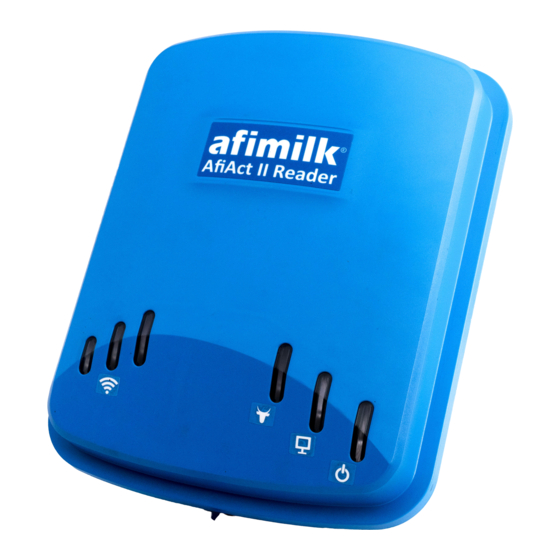
Introduction Chapter 1 1.4 AfiAct II Reader – Indicators and I/Os The following sections describe the Reader’s indication LEDs, input and outputs. 1.4.1 Front Panel ‐ LED Indications The following image shows the Reader’s fault and indication LEDs. 1. Tag communication available/not available LED indication 4. Wi‐Fi signal strength 2. PC: Indication of indication LEDs communication with AfiAct II application 3. Power ON Table 1‐4.External LED Indications Item LED Label Description 1 Tag Comm Communication with tags: Blinking Yellow – good communication Off – No communication Note: This LED blinks for a short period every time a tag message is received in the Reader. 2 PC comm Communication with the PC AfiAct II application Yellow – The Reader is communicating with the AfiAct II Off –Reader could not connect with AfiAct II During firmware upgrade: PC comm LED and the lowest Wi‐Fi signal strength LED blink ... -
Page 19: Back Panel - Inputs And Outputs
Introduction Chapter 1 1.4.2 Back Panel – Inputs and Outputs The following image shows the Reader’s Back panel inputs and outputs. Connection to PC communication Input power cable Power cable: AC Connection – Blue and Brown DC Connection – Red (+) and Black (‐) Note: when the communication is not in use, close the connection using the cap! 1.4.3 Reader box ‐ Attributes Label On top of the Reader’s cable cavity you will find the following label, indicating the Reader’s attributes Reader’s Unique ID (UID) Page 6 AfiAct II™ Installation Manual June 2016... -
Page 20: Afiact Ii Reader Power Specifications
Introduction Chapter 1 1.5 AfiAct II Reader Power Specifications The AfiAct II Reader power connection must comply with the following specifications: Table 1-5.Power Specifications Item LED Label Voltage Nominal voltage of 24Vac (minimum 21.6Vac to maximum 27.5Vac) Current AC: 0.6A max 50/60Hz DC: 1A max Power per unit 16.5 Watts (i.e. a VA rating of at least 20 VA for the transformer) To avoid unacceptable electrical power reduction, the cable length and diameter must be validated, to ensure the cable is not too long per its . ... -
Page 21: System Installation Overview
Introduction Chapter 1 1.6 System Installation Overview To fully install AfiAct II system, pre‐installation preparation is needed; some preparations are done by Dealers’ technicians, and others are the farmer’s responsibility. The following flowchart presents the preparation and installation phases and the responsible party per phase. Determine reader mounting point, see 2.1 Set network coverage (wired / Wi‐Fi), see 2.2 Plan & prepare site Prepare PC prerequisites, see 0 In parallel Install and set AfiAct II Attach tags to cows, software, see 3 see 6 In parallel AfiAct II Reader initial Enter cow data into communication, see 4 system (done by the farmer), see Appendix F Mount the Reader in the cowshed, see 5 System is installed Page 8 AfiAct II™ Installation Manual June 2016... -
Page 22: Prerequisites And Site Planning
Prerequisites and Site Planning Chapter 2 Prerequisites and Site Planning Before starting AfiAct II installation, verify that all pre‐requisites are fulfilled: 1. Reader mounting point: Identify a proper location for AfiAct II Reader, see 2.1 2. Verify network coverage in the required area, see 2.2 Note: It is highly recommended that the network technician be present during the Reader installation. 3. Verify system deployment is scratch; (if using a standalone system side‐by‐side with AfiFarm, you may want to restore the initial animal database to the system after the installation). 4. Validate AfiAct II PC corresponds with the requirements, see 0 2.3 To determine the system sampling sessions during the installation, investigate the specific site needs. This can be performed during the preparations phase, or during the installation, see 4.2.2. ... - Page 23 Prerequisites and Site Planning Chapter 2 Optional reader positioning location The Reader mounting location is based on the cowshed size and location, and should comply with the following conditions: Height: The Reader is mounted on a pole, maximum height from the ground: 3 meters high from the ground. Coverage (tags and Wi‐Fi/wire): (fine‐tuning will be performed while mounting) The mounting pole location must allow tag‐coverage range for the whole defined area. This is determined according to the shed scheme, and will probably be around the center of the required 80 meters coverage radius, also covering the feeding and water trough areas. The final coverage and corresponding location determination must be done during a site survey and could vary according to specific farm environment. The Reader should have a line of sight towards cow tags, with minimal interference from other sheds/poles/buildings, etc. The Reader should have Wi‐Fi / wired connectivity to the Access Point / office. If located under a roof, avoid transmission interference, according to the following specifications: The structure may be made of metal or wood. The roof should be at least 4 meters high; If possible, the roof should be made of a plastic material (rather than aluminum or sheet metal). If the sides are closed, this siding material should not be metal either. Page 10 AfiAct II™ Installation Manual June 2016...
-
Page 24: Setup Network And Power Coverage
Prerequisites and Site Planning Chapter 2 If metal fencing is used to keep animals out, it should be a large opening Australian‐type fencing material (at least 30 cm) (otherwise the communication signals may be reduced). Power access: The pole has near access to a power outlet (to be provided by the farmer). Accessibility: The Reader and power box can be easily viewed and accessed for maintenance (if possible – accessible from the passage). Weather protection: The Reader is fully outdoor compatible. The Reader must be fixed to a static connection point. Do not fix the reader on a connection point that vibrates or moves as a result of ventilating fans, blowers, motors and machinery. 2.2 Setup Network and Power Coverage The customer may determine the type of network communication used between the PC and the Reader; either wired or Wi‐Fi can be used. However, it is the customer’s responsibility to ensure power point and network coverage in the office and in the Reader‐determined mounting point (in the cowshed – according to the Dealer’s technicians).In either case, the office and Reader network coverage setup must be completed and tested before starting the Reader installation (e.g. via a laptop computer, smartphone, or in future releases,via tag‐indicator). Note: The Wi‐Fi network must in turn provide an IP to the Reader’s MAC address. Office Wi‐Fi Coverage The office Wi‐Fi coverage is a recommendation, and it is required when configuring the Reader to work with the AfiAct II software. PC to Reader Wi‐Fi coverage The Reader’s network coverage is set after determining the Reader installation point in the cowshed. The following figure shows an example of network coverage in the office and cowshed. Wi‐Fi Access Point ... - Page 25 Prerequisites and Site Planning Chapter 2 Wired connection towards office Wi‐Fi router Wi‐Fi Specifications Item Value Network TCP/IP protocol network Network shall have an operative DHCP server Any commercial access point Carrier grade (99.999% service). Access Point Any commercial access point. In case of an OUTDOOR installation – outdoor weatherproof grade according to the installation environment and lightning protection design. Carrier grade (99.999% service). WiFi certification 802.11g (802.11n is supported only if it can be set to work with supports 2.4 GHz bandwidth) Encryption method Preferable: WPA‐PSK/WPA2‐PSK default The following methods are also supported: WEP, WPA/WPA2, WPA‐PSK/WPA2‐PSK and IEEE 802.1X standard Preferable SSID afiact2 Preferable password afimilk123 The SNR at Reader mounting point must be greater than 15 dB. Signal and Noise RSSI must be higher than ‐80dBm. Note: Preferred RSSI is ‐65 dBm to ‐55 dBm in the designated ...
-
Page 26: Prepare The Pc Environment
Prerequisites and Site Planning Chapter 2 2.3 Prepare the PC Environment Before starting to install AfiAct II software, verify that your PC corresponds to the following set of requirements: The computer uses a supported operating system, Processor and Memory see 2.3.1 Network connections comply with the requirements, see 2.3.2 Additional Windows OS preparations, see 2.3.3 Verify the PC is prepared, see 2.3.4 These requirements are detailed in the following sections. Verifying that you are using correct computer settings is essential for performing the installation correctly, allowing correct operation of AfiFarm5. In systems where there is a network administrator, he or she must be present during the installation. It is highly recommended to have an internet connection, to allow efficient support when needed. Page 13 AfiAct II™ Installation Manual June 2016... -
Page 27: Verify Operating System, Processor &Memory
Prerequisites and Site Planning Chapter 2 2.3.1 Verify Operating System, Processor &Memory The PC minimum requirements are as follows: Operating system (Windows edition): MS Windows 7 – Professional 64 bit MS Windows 8.1 ‐ Professional 64 bit Memory, processor and other requirements: review your specific needs according to the farm type and according to the installed operating system, as detailed in the following table. Table 2‐1. Server PC Requirements Operating system Windows7 PRO (64‐bit) ; Windows8.1 PRO (64‐bit) No. of animals Up to 1000 1000 ‐ 5000 More than 5000 RAM(GB) Min: 16 Min: 32 Min: 32 Recommended: 32 Recommended: 32 Recommended: 32 Processor i5 i7 i7 HD type 7200 RPM 64MB cache / 7,200 64MB cache / 10,000 RPM ... - Page 28 Prerequisites and Site Planning Chapter 2 2.3.1.1 Verify RAM and Processor To verify required RAM and Processor: 1. In your system tray, click the Start icon , and select Control Panel 2. Click System. Page 15 AfiAct II™ Installation Manual June 2016...
- Page 29 Prerequisites and Site Planning Chapter 2 3. Verify the following attributes are in accordance with requirements (see 2.3.1): Windows edition Processor System Type RAM Page 16 AfiAct II™ Installation Manual June 2016...
- Page 30 Prerequisites and Site Planning Chapter 2 2.3.1.2 Verify HD Free Space and Type If the installation is done in a folder that is not the installation folder – verify that there is enough disk space in BOTH disks. To check your HD free space 1. In your system tray, click the Start icon , and Double‐click on computer Click 2. Check free space on your hard drive. Free space Page 17 AfiAct II™ Installation Manual June 2016...
-
Page 31: Network Connections
Prerequisites and Site Planning Chapter 2 2.3.2 Network Connections AfiFarm5 Network connections must comply with the following conditions: The network is supported by Windows. The network supports TCP/IP. The network must be transparent for a UDP broadcast. The LAN must have a minimum speed of 100 MBps. In order to print reports, the system must have a printer, connected either directly to the PC or via the network. Page 18 AfiAct II™ Installation Manual June 2016... - Page 32 Prerequisites and Site Planning Chapter 2 To verify your system has correct network connections 1. In your system tray, click the Start icon , and select Control Panel 2. Click Network and Sharing Center. Page 19 AfiAct II™ Installation Manual June 2016...
- Page 33 Prerequisites and Site Planning Chapter 2 3. In the Network and Sharing Center dialog, verify that the Network is set to Home 4. If the Network is not set to Home, click on the network value. The Set Network Location dialog appears. 5. Choose Home Network and close the dialog. Page 20 AfiAct II™ Installation Manual June 2016...
-
Page 34: Additional Windows Os Preparations
Prerequisites and Site Planning Chapter 2 2.3.3 Additional Windows OS Preparations 2.3.3.1 Configure Power Settings 1. In your system tray, click the Start icon , and select Control Panel Page 21 AfiAct II™ Installation Manual June 2016... - Page 35 Prerequisites and Site Planning Chapter 2 2. Click Power Options. 3. Checkmark Balanced and click Change plan settings. Click Checkmark Page 22 AfiAct II™ Installation Manual June 2016...
- Page 36 Prerequisites and Site Planning Chapter 2 4. Click Change advanced power settings. 5. Expand the Hard disk folder (click the +sign near the folder). Then expand Turn off hard disk after and change to Never. 6. Expand Sleep. Then expand Sleep after and change to Never. Click to expand Click to change folders value to Never Page 23 AfiAct II™ Installation Manual June 2016...
- Page 37 Prerequisites and Site Planning Chapter 2 2.3.3.2 Install Windows Updates 1. In your system tray, click the Start icon , and select Control Panel 2. Click Windows updates Page 24 AfiAct II™ Installation Manual June 2016...
- Page 38 Prerequisites and Site Planning Chapter 2 3. Click Install updates and follow the windows wizard to install all available updates. Click to install windows updates 4. Click Change settings. Page 25 AfiAct II™ Installation Manual June 2016...
- Page 39 Prerequisites and Site Planning Chapter 2 5. In the displayed dialog, choose Check for updates but let me choose whether to download and install them. 6. Click OK to return to Windows update dialog. 7. Click View update history. 8. Check the status column for any problems and fix if necessary (refer to vendor instructions). Page 26 AfiAct II™ Installation Manual June 2016...
- Page 40 Prerequisites and Site Planning Chapter 2 2.3.3.3 Set the Time and Synchronization Disable the synchronization with the internet time server and check the time zone settings as follows: 1. In your system tray, click the Start icon , and select Control Panel 2. Click Date and Time Page 27 AfiAct II™ Installation Manual June 2016...
- Page 41 Prerequisites and Site Planning Chapter 2 3. Click Change time zone 4. Uncheck Automatic adjustment of daylight saving Time. Uncheck 5. Verify that the time zone settings are identical in all the used PCs (in a multi PC system) (in the above example, all PCs should be set to the same time zoneUTC+02:00) Page 28 AfiAct II™ Installation Manual June 2016...
- Page 42 Prerequisites and Site Planning Chapter 2 2.3.3.4 Confirm the File Sharing and Network Discovery Verify proper file sharing setup as follows (for a multi PCs system): 1. In your system tray, click the Start icon , and select Control Panel 2. Click on Network and sharing center. Page 29 AfiAct II™ Installation Manual June 2016...
- Page 43 Prerequisites and Site Planning Chapter 2 3. Click Change advanced sharing settings. 4. Expand Home or Work (click the arrow ) Expand Turn ON 5. Verify the following attributes are turned ON: Network discovery is ON. File and printer sharing is ON. Access to read and write files in Public folders for anyone with network access is ON. Using user accounts and passwords to connect to other computers is ON. Page 30 AfiAct II™ Installation Manual June 2016...
-
Page 44: Verify System Is Prepared
Prerequisites and Site Planning Chapter 2 2.3.4 Verify System is Prepared As the successful completion of the installation process is strongly dependent on the environmental preparations previously performed, it is essential at this phase, before starting to install the system, that the user performs preparations checkup. Review the pre‐requisites list and verify that all of them were implemented. What Next? Your system is now ready for installation. Page 31 AfiAct II™ Installation Manual June 2016... -
Page 45: Install And Set Afiact Ii Software
Install and Set AfiAct II Software Chapter 3 Install and Set AfiAct II Software AfiAct II software is installed on a single PC. It consists of two installed modules: AfiFarm5 – contains the AfiAct II program and reports. In farms that do not use other AfiFarm elements, the data entry screens and activities are also accessed through this component. AfiControl RT module– this module controls and monitors the system and collects data from the animals through the Reader. This chapter details the installation phases of the two modules: 1. When upgrading an existing system only: Backup existing database, see 3.1 2. Install AfiFarm5 and the RT (Real Time) system, see 3.2 3. When using a standalone system side‐by‐side with existing AfiFarm: Restore backed‐up data, see Appendix E 3.1 For existing AfiFarm: Manual Data Backup This section describes steps performed ONLY when installing a stand‐alone AfiAct II system, that will run side‐by‐side with an existing system from releases 4.x; If your system is installed from scratch – continue to section 3.2 Before starting the installation, backup the database and configuration parameters manually. This process takes time: between 0.5 – 3 hours, depending on the database size and on the specific PC performances. Page 32 AfiAct II™ Installation Manual June 2016... - Page 46 Install and Set AfiAct II Software Chapter 3 To backup AfiFarm database: 1. Insert the USB flash drive to which the database will be backed‐up into the server PCs’ USB connector. 2. Click Tools and select Backup from the drop down menu. 3. In the Backup dialog that appears, select the Full radio button, then click the folder icon to browse and navigate to your backed‐up database location. Then click Start. Click to browse and Select select database Click to start backup location database backup Page 33 AfiAct II™ Installation Manual June 2016...
-
Page 47: Install Afifarm5 And Aficontrol
Install and Set AfiAct II Software Chapter 3 3.2 Install AfiFarm5 and AfiControl This section details the AfiAct II installation steps, as performed by following the instructions of the installation wizard. The wizard installs both AfiFarm5 and AfiControl RT (Real Time) modules (including the FarmServer Setup; Real Time Setup (RTMS); Real Time GUI (RTG); Real Time Station Controller). To install the AfiAct II modules follow these steps: 1. Review general notes before starting, see 3.2.1 2. Install the HASP (software license key), Initiate and follow the installation wizard steps, see 3.2.2 Page 34 AfiAct II™ Installation Manual June 2016... -
Page 48: General Notes
Install and Set AfiAct II Software Chapter 3 3.2.1 General Notes Before starting, review the following general notes. Installation time The installation time varies according to the specific PC characteristics and specific issues or wrong configurations. Generally: clean installations may take around 50 minutes. Process sub‐steps During the installation, the wizard automatically performs several steps, as required by the specific scenario. These include the installation of various components (SQL, .Net 4, drivers, database operations, configurations, etc.). Note: In AfiAct II’s AfiFarm5, the AfiFarm configuration is done via AfiControl RT System. While the main steps for the configuration are described in this manual (see Appendix C), an additional and more detailed description of the tool usage is provided in AfiConrol configuration manual (see referred documents, page viii). Installation dialog layout The following main dialog appears during the installation, displaying various messages and indications, allowing the user to follow the background phases. In addition, the lower area provides information on the overall installation progress: Event currently in progress Progress bar Current installation phase The installation procedure might vary slightly for different operating systems. Page 35 AfiAct II™ Installation Manual June 2016... -
Page 49: Set & Initiate The Installation Wizard
Install and Set AfiAct II Software Chapter 3 3.2.2 Set & Initiate the Installation Wizard After verifying your PC is prepared for installation (see 2.3.4), initiate the installation wizard according to the following steps. Screens that are displayed by the wizard but do not require user actions are not always presented in this section. Such screens that appear are NOT TO BE TOUCHED. 1. Insert the provided AfiFarm5 HASP USB key into the USB port of the PC. 2. Open AfiFarm5 DVD and double‐click on the installation file:UnifiedSetup. Double‐Click 3. The installation wizard is launched. The installation type dialog opens: choose Install. Page 36 AfiAct II™ Installation Manual June 2016... - Page 50 Install and Set AfiAct II Software Chapter 3 4. Click Next. The PC Deployment Mode dialog opens. Select All in one deployment type (i.e. all components are on the same PC) Note: Custom installations (i.e. user‐selected components are to be installed on the current computer) is not relevant for AfiAct II installations Select 5. In the following screen: Type in your currently used Windows account username and password Note: If no password is used, leave the password field empty! Click Next Page 37 AfiAct II™ Installation Manual June 2016...
- Page 51 Install and Set AfiAct II Software Chapter 3 6. The following message appears; Click OK Page 38 AfiAct II™ Installation Manual June 2016...
- Page 52 Install and Set AfiAct II Software Chapter 3 7. In the following screen, select Install. 8. Click Next. The welcome dialog opens. Make sure you close any programs running in the background. Page 39 AfiAct II™ Installation Manual June 2016...
- Page 53 Install and Set AfiAct II Software Chapter 3 9. Click Next. The License Agreement dialog opens Select 10. Select I accept the agreement and click Next. The Functionality dialog opens Page 40 AfiAct II™ Installation Manual June 2016...
- Page 54 Install and Set AfiAct II Software Chapter 3 11. Choose Server and click Next. The system searches the local network to ensure there are no other servers found. When done searching, the Next button becomes available. If a server has been detected, the problem must be resolved before continuing the installation. Contact Afimilk helpdesk, see page ii. 12. Click Next. The Drive dialog opens. Page 41 AfiAct II™ Installation Manual June 2016...
- Page 55 Install and Set AfiAct II Software Chapter 3 13. Select the hard drive where AfiFarm files are to be installed. This is the hard drive previously prepared, where there are at least 100GB of free space available (see 2.3.1.2). Click Next. The Number dialog opens: 14. Select a unique computer number for the computer you are installing (default: #1) 15. Click Next. The Password dialog opens, where the default password is afi. Important Note: do not enter any value in this screen! Page 42 AfiAct II™ Installation Manual June 2016...
- Page 56 Install and Set AfiAct II Software Chapter 3 16. To keep your existing password: do not type any value into the boxes. To change the password: type the new password. Then re‐type your password in the Confirm password box. 17. Click Next. The Language dialog opens, where the default language is check‐ marked in gray (in the following example: Vietnamese). 18. Select the desired language(s) and click Next. The Summary dialog opens Page 43 AfiAct II™ Installation Manual June 2016...
- Page 57 Install and Set AfiAct II Software Chapter 3 19. Click Finish. The automatic installation process starts, and the following dialog appears and the SQL files are installed. (This may take a few minutes). 20. The system requests permission to restart: Click Restart Now or wait for the auto‐restart. Page 44 AfiAct II™ Installation Manual June 2016...
- Page 58 Install and Set AfiAct II Software Chapter 3 Continue to Supervise Automatic Installation Steps 21. After rebooting, a few progress screens appear, while the system installs the required elements. The system requests permission for rebooting a few times. This process may take 10‐15 minutes. Make sure that the progress indications show (slow) progress. IMPORTANT! Do not touch any of the screens shown during the process! 22. When the process ends, the following dialog appears. Click Close. 23. AfiFarm will automatically open 24. AfiControl installation is complete. If using a standalone system side‐by‐side with existing AfiFarm, you may need to restore the initial animal database to the system at this phase. This rare scenario is detailed in Appendix E. Page 45 AfiAct II™ Installation Manual June 2016...
-
Page 59: Initial Reader Communication
Initial Reader Communication Chapter 4 Initial Reader Communication It is recommended that the AfiAct II Reader initial connection is performed immediately after the AfiAct II SW was installed. Before mounting the Reader, connect the Reader to the local network (same network as the computer) via a network cable, and verify connectivity with the AfiControl RT system. AfiControl locates the Reader’s MAC and IP to perform a handshake (RT sends a broadcast message searching for the Reader unique ID; then the Reader replies to the sender (RT) providing its IP address). Setting the Reader initial communication includes the following steps: 1. Connect the Reader to the wired network, see 4.1 2. Configure AfiControl mandatory parameters (quick start), see 4.2 3. Verify communication (handshake) via AfiControl, see 4.3 4. If Wi‐Fi is used, connect the Reader to the Wi‐Fi network, see 4.4 After each Reader restart, wait until the Reader’s internal boot LED is blinking, see Error! Reference source not found. Page 46 AfiAct II™ Installation Manual June 2016... -
Page 60: Connect The Reader To The Wired Network
Initial Reader Communication Chapter 4 4.1 Connect the Reader to the Wired Network A network cable is used for connecting the Reader to the PC. Then the Reader is connected to the power source, and the connectivity is verified via AfiControl. To connect the Reader to the network and obtain an IP address 1. Connect network cable: connect a network cable to the Reader’s back‐panel network connector. Connect the other side of the network cable to the PC USB connector. PC communication cable: Towards PC USB Connect PC communication cable 2. Connect to power (temporary connection): Use the power supply transformer box to power the Reader on: a. Use the AC terminal block (Brown and Blue) at the edge of the reader’s power cable, and connect it to the power transformer box white cable. If needed – strip the insulation to expose cable edges. To power outlet Input power cable AC Connection – Brown and Blue b. Connect the transformer box to the power outlet. ... - Page 61 Initial Reader Communication Chapter 4 c. Turn on the transformer box switch, and verify that the Reader’s LEDs are on. Turn ON 3. If a DHCP exists and is configured to provide a dynamic IP to the Reader, the Reader will automatically obtain an IP. If not, the Reader will use the factory IP address 172.20.1.1. If the Reader does not show correct network connection, restart the reader by turning the power off and on again. Ensure taking all precautions when working with the high voltage components. Page 48 AfiAct II™ Installation Manual June 2016...
-
Page 62: Set Aficontrol (Quick Start)
Initial Reader Communication Chapter 4 Set AfiControl (Quick Start) AfiAct II components are connected via the network (wired or wireless), where AfiControl manages the communication between the components (AfiAct II software, Reader, etc.). AfiControl’s client‐server architecture involves three types of computer functions, all running on the same PC for AfiAct II: Server (manages herd database, system configuration and licensing); Controller (manages the real‐time processes, and includes a small database to control the stations and collect data when the communication with the server is interrupted), Client (for user access to herd data). To allow basic system functionality and overall system communication, the following basic parameters must be set in AfiControl for quick‐start: HW system layout: PCs, devices (e.g. Reader(s) Unique ID), adaptors, ports, etc.) Logical system definitions, reflecting the stations (i.e. AfiAct, AfiSort, milking‐ parlors,…), sites (aggregation of all the stations with the same identification system – usually geographically close to each other), tracks (monitored animals; heifers/milking cows) and required sampling sessions. Deployment of the software to support the previously defined site(s) (in this case: AfiAct II) via the tray configurator. The following sections provide an overview of AfiControl navigation, session‐ definition requirements, and explain how to set up the mandatory system fields via AfiControl. For better system monitoring, it is recommended to define a user report that detects tags not assigned to animals), see Appendix C. The setup done via the RT System interface is checked at a later stage, when the whole system is connected (including the Reader, see 4.2). The AfiFarm RT system is a powerful tool, allowing the technician to perform Reader settings, tags identified by the system, view map of connected network ... -
Page 63: Navigating Aficontrol Tool
Initial Reader Communication Chapter 4 4.2.1 Navigating AfiControl Tool AfiControl includes two accessible GUI elements: The AfiControl screens – for configuring the system, managing reports, etc. The Station Controller screens – used for: Deployment of the specific‐site‐type supporting software (here: AfiAct II) Monitoring connections with the defined system sites AfiControl screens are accessed via the AfiControl icon , and include the following areas (see Appendix C for details) Ribbon control tabs Selected ribbon‐tab’s sub‐options Network map, Reports window Main display: selected report, configuration parameters, etc. The Station Controller screens are accessed from the icon in the system tray and display the monitoring screen (connected sites) and the configuration screen (connecting to server host): Page 50 AfiAct II™ Installation Manual June 2016... -
Page 64: Determine The Required Sampling Sessions
Initial Reader Communication Chapter 4 Configuration screen: Selecting host (i.e. previously defined site type) for corresponding SW deployment Monitoring screen: Expand to see Connected applications defined sites list Note: the above configuration screens are only relevant AFTER the system has been configured! 4.2.2 Determine the Required Sampling Sessions To allow AfiAct II algorithms to analyze the data correctly, the system must be set to reflect the specific farm monitoring needs. These are set by the following parameters: Tracks –Determine the type of animals that are monitored (i.e. heifers/cows), and the times in which they are monitored (i.e. sessions, see below). Stations – Determine the specific monitored activity: milking, AfiAct II, AfiSort, etc. Sites – The group of stations in the same geographical area, using the same identification system Sessions – The sessions are set to reflect the specific farm’s daily scheduled activities. (E.g. milking times, breeding times, pasture times, feeding times, and other activities done in the farm). To determine the above parameters correctly, the dealer personnel together with the farmer must collect and consider the relevant information. The following items provide guidelines for determining the farm’s sessions via AfiControl. Fine tuning may be done after running the system for a test period. ... - Page 65 Configure the high activity session for 1.5 hours before the high activity occurs, and up to 1.5 hours after the high activity occurs. 4. The recommended number of sessions per day is between 1 and 3. 5. The session times must be continuous, ensuring 24 hours coverage If the session intervals or schedules are changed, contact Afimilk representative to re‐configure the system. For TieStall sessions refer to Appendix D ...
-
Page 66: Set System Mandatory Parameters
Initial Reader Communication Chapter 4 4.2.3 Set System Mandatory Parameters To define the system computers (server and system controller) 1. Verify that the Station Controller is up and running by checking the icon in the system tray 2. Open the AfiControl system (click the icon). 3. The login screen appears. Enter the following login attributes: Server: localhost User: admin Password: admin Page 53 AfiAct II™ Installation Manual June 2016... - Page 67 Initial Reader Communication Chapter 4 To define the new AfiAct II site 4. In the displayed AfiControl main screen, under the Settings tab, select Configurator from the tab sub‐options. Select 5. In the displayed Configurator screen, right‐click on New Farm and select the Add New PC button. Double‐click on the new PC presented, to display its sub‐ elements Right‐click Select Double‐click to expand Page 54 AfiAct II™ Installation Manual June 2016...
- Page 68 Initial Reader Communication Chapter 4 6. Right‐click on Controller, select AddAdd AfiAct II from the displayed roll‐ down site‐types menu. Select Right‐click Select Page 55 AfiAct II™ Installation Manual June 2016...
- Page 69 Initial Reader Communication Chapter 4 7. The New Controller for AfiAct II is added. Expand the controller to configure its parameters, where RF region channel is set to 1 by default, and must not be changed. Expand Do not change the channel! If the channel is changed, you must change the Tags channels as well! Page 56 AfiAct II™ Installation Manual June 2016...
- Page 70 Initial Reader Communication Chapter 4 Set the Reader(s) and Ports 8. In the Readers area, click to add a reader, enter the Reader UID (as obtained from the label on the Reader, see 1.4.3). Then enter a Reader name and click Example: Click Click Enter reader ID (as appears on the reader’s label) Note: If the system includes more than a single Reader, enter all of the Readers’ UIDs and names. Page 57 AfiAct II™ Installation Manual June 2016...
- Page 71 Initial Reader Communication Chapter 4 9. Set the relevant parameters The following parameters are available: Tag transmission interval ‐ sets the interval in which the tags send their data to the Reader (default 15) AfiFarm/Reader Communication Timeout – not to be changed (default 3) Diagnosis Sending Interval – not to be changed (default 255) Channel Scanning Interval – not to be changed (default 255) RF Region – determines the transmission region (e.g. USA; Europe…) with its relevant frequency range. When clicked – a corresponding frequency channel table opens, allowing the user to select a different channel (in case of interferences). The default channel is set to 1 for all regions; your tags are factory‐set to the same default channel as the Reader. The reader and the tags must be set to the same frequency channel. Therefore ‐ do not change the channel! If the channel is changed, you must change the Tags channels as well. Technicians may manage frequency via the Tag Reading/Programming Unit (RPU). For tag channel update see Appendix B ...
- Page 72 Initial Reader Communication Chapter 4 10. Select your RF Region and relevant working channel. In the example below, the Europe channels are shown. Do not use 868.8 and 869 for Europe Frequencies 868.8 and 869 must not be used for Europe. Page 59 AfiAct II™ Installation Manual June 2016...
- Page 73 Initial Reader Communication Chapter 4 Set the required track(s) (tracking sessions and tracked animals) for the defined station 11. Under the SettingsConfigurator tab, select the Tracks radio button. The displayed screen shows the following main areas: Track management area Defined stations area Sessions definition area Defined Stations area Track management area Session definition Page 60 AfiAct II™ Installation Manual June 2016...
- Page 74 Initial Reader Communication Chapter 4 12. Set the required track attributes as follows: Select the type of animals to be tracked (Milk cows or Heifers). Enter a meaningful name to the track Choose tracked animal Name the Track Page 61 AfiAct II™ Installation Manual June 2016...
- Page 75 Initial Reader Communication Chapter 4 13. Add the AfiAct II station to your track, as follows: Select (highlight) the defined track In the station definition area, click the sign. Choose the Act station from the roll‐down list Note: To remove a station, select the required station and click the sign Choose the Act station 14. Define sessions for each defined track, corresponding to the farm schedule (Heifers will usually require only one or two sessions) as follows: In the station definition area, select the station to be updated (in this example: Act on Test contrl). In the session definition area, click the sign to add a session. Repeat this to add the required number of sessions (in the following example: 3) If the sessions are not distributed evenly during the 24 hours: For each session, select the time in which the session starts. Note: To remove a session, select the required session and click the sign Page 62 AfiAct II™ Installation Manual June 2016...
- Page 76 Initial Reader Communication Chapter 4 Click to add a session for the track 15. When done updating, click Commit . A confirmation window appears. Click to confirm changes When done, click to commit changes 16. Click Yes to approve changes, Then wait a few seconds while AfiFarm restarts , and until all the processes are up and running. Page 63 AfiAct II™ Installation Manual June 2016...
- Page 77 Initial Reader Communication Chapter 4 Deployment of the software according to the defined station (i.e. AfiAct) 17. Open the Station Controller manager by clicking the icon in the system tray . The following dialog appears Click . Click settings. The following Station Controller Settings dialog appears Note: you may also choose Re‐install All button to restart the procedure. Click . Enter the following attributes: Server: localhost Click the Get Host button. Page 64 AfiAct II™ Installation Manual June 2016...
- Page 78 Initial Reader Communication Chapter 4 20. In the updated dialog, from the available list of hosts (i.e. computers with defined controllers), select the desired Host (in this example: AfiPC‐USER2). Click 21. Click the Set host button. The software configuration corresponding to the selected‐defined track‐station is now installed, and the above settings window is auto‐closed. 22. In the Station Controller manager (if not already open – re‐open by clicking the icon in the system tray . The following monitoring info appears Defined & connected site 23. You will now be able to monitor the software that manages the defined Reader. (If the defined controller is not displayed, you may click Reset All). Note: after configuring the station controller, when connecting the Reader, the Reader’s PC comm. LED should indicate communication between the Reader and PC. Page 65 AfiAct II™ Installation Manual June 2016...
-
Page 79: Additional Aficontrol Configurations And Monitoring
Initial Reader Communication Chapter 4 4.2.4 Additional AfiControl Configurations and Monitoring For better system monitoring, it is recommended to perform some basic settings: The system performs automatic backup. If needed, you may perform a manual backup via the AfiControlTools tabBackup sub‐option: Verify that the newly defined site appears as an icon in the AfiControl System view: Click on the System view tab Click on the AfiAct site to verify that it is connected; if the site is connected: the Reader name and IP_Address will be displayed. Click Click Verify reader IP appears Check the list of faulty tags: Click ReportsTagsTags Malfunction Click Customize the system to your specific farm. Page 66 AfiAct II™ Installation Manual June 2016... -
Page 80: Verify Reader & Aficontrol Communication
Initial Reader Communication Chapter 4 These setups may be fine‐tuned or updated at any time after mounting the Reader. For details on system configurations and maintenance via AfiControl, refer to Appendix C. Before the system may be used for detecting cows in heat, average behavior performance baseline should be generated by the application. This can take 5 to 6 days. 4.3 Verify Reader & AfiControl Communication To ensure that the Reader handshake has been successful 1. (If not already open), open AfiControl (click the icon). 2. Click on the System view tab Click on the AfiAct site to verify that it is connected if the site is connected: the Reader name and IP_Address appears. Click Click Verify reader IP appears 3. The connected elements (readers) are most likely to appear as disconnected (with a red sign: ) during the first few seconds. Page 67 AfiAct II™ Installation Manual June 2016... -
Page 81: If Needed: Set Wi-Fi Communication
Initial Reader Communication Chapter 4 4. Wait a few seconds for the reader‐controller connection to be established. When the connection is established, AfiControl will show the reader as connected, with its relevant IP address, indicating that the Reader and AfiControl Controller are now communicating. In addition, the Reader’s PC Comm LED will show that the Reader and PC are communicating. Write down this reader’s dynamic IP address. Note: When there is no DHCP mechanism, you may use the Reader’s default static IP address 172.20.1.1 for back‐to‐back connection, see 7.5 For troubleshooting ‐ The Reader is provided with a label showing its ID (and MAC), to which an IP address will be assigned during the connection procedure. You may obtain the IP address that has been assigned to your Reader, by using a standard IP/MAC scanner application (e.g. ip‐scanner). 4.4 If Needed: Set Wi‐Fi Communication If the Reader is to use Wi‐Fi communication, the Reader should be connected to the Wi‐Fi network at the office, before proceeding with the Reader mounting. By default, the reader uses credentials detailed in section 2.2 (also listed below); therefore, it is recommended that – if possible – the Access Point wireless settings are set according to these defaults. In this setup, the Reader automatically connects to the wireless network. To use default reader credentials Set the Access Point wireless to the following: • SSID (access point name): afiact2 • Encryption method: WPA‐PSK/WPA2‐PSK2 • Password: afimilk123 If, for some reason, the Access Point cannot be set according to the above defaults, set the reader to use different credentials (refer to 4.4.1) If there is NO Wi‐Fi coverage in the office, the Wi‐Fi network assignment will be set in the office as shown below, and the verification will be performed in the shed (Wi‐Fi communication LEDs). ... -
Page 82: Set Reader To Use Wi-Fi Settings Different Than Default
4.4.1 Set Reader to use Wi‐Fi settings different than Default When Access Point setup differs from default credentials, setup the Wi‐Fi communication via the Reader’s direct Wi‐Fi networking GUI application (Luci), (accessed via the PC browser), which allows manual management and troubleshooting of the connection between the Reader’s main board and the local network (e.g: entering the Wi‐Fi network SSID (Service Set Identifier) manually). To set the Reader Wi‐Fi credentials (not as in default) via LUCI interface 1. Open your PC browser and access the Reader interface by typing in the browser’s navigation bar the IP address obtained from the Reader’s map: http://reader_ip_address (Note: If there is no automatic address (DHCP), and the default factory address is used, you may also enter the following IP address: http://172.20.1.1) The login screen appears: Click to login Login Enter username area and password 2. Enter the Reader username and password (default: user: root, password: afimilk).Then click the button. 3. In the displayed Reader communication options, select the tab from the navigation options and choose Interfaces Navigation‐ tabs Select to access network options Page 69 AfiAct II™ Installation Manual June 2016... - Page 83 Initial Reader Communication Chapter 4 4. To ensure that the connection to the wireless network is generated with the correct parameters, clear the default wwan interface as follows: Scroll to the row, and click the 5. Under the Network tab sub‐options select Wi‐Fi , and click the (OR ) button at the bottom of the page to obtain the list of available Wi‐Fi networks. Click to scan for available networks 6. From the displayed list of available networks, select the requested network and click the button. Selected network Click to connect to the selected network Page 70 AfiAct II™ Installation Manual June 2016...
- Page 84 Initial Reader Communication Chapter 4 7. If the network is secured, the system will wait for the user to enter the protocol used and the password. Type the Wi‐Fi Network password in the correct place: It is the user’s responsibility to verify that the correct password had been entered. Entering a wrong password will end with no network connection, and the whole process will need to be performed again (starting at phase 1 above). Page 71 AfiAct II™ Installation Manual June 2016...
- Page 85 Initial Reader Communication Chapter 4 8. Click at the button to submit the new configuration. Click to connect to the selected network 9. In the displayed screen all the details that will be sent to the device are displayed. Roll down and click Save & Apply. Page 72 AfiAct II™ Installation Manual June 2016...
- Page 86 Initial Reader Communication Chapter 4 10. Wait until the system is connected. Note: If the connection takes too long (more than 3 minutes), restart the Reader (POWER OFF and then back ON. 11. Verify that all the Wi‐Fi LEDs (WLAN & signal strength) on the Reader are ON (see 1.4.1). If the Wi‐Fi LEDs don’t work then you will have to start this stage from the beginning. 12. After connecting to the wireless network, disconnect the network cable and re‐ start the Reader: a. Use the transformer power button to turn the device off. b. Disconnect the network cable. c. Power the Reader ON using the transformer switch d. Wait for the device to locate the network (~1 minute). e. The communication verification is now done by checking:: At least 2 communication LEDs are ON AfiControl displays the Reader’s IP, see 4.2 f. Close the Reader configuration interface (browser) Initial Reader communication is complete. Disconnect and Take the Reader to the Shed. Page 73 AfiAct II™ Installation Manual June 2016...
-
Page 87: Mount The Reader
Mount the Reader Chapter 5 Mount the Reader After configuring the Reader, mount the Reader and its power elements in the location determined previously (see 2.1, 2.2), after verifying that there is both tag and network coverage in the cowshed (Wi‐Fi or cable, as determined by the customer). Cowshed roof Bracket arm Reader Power outlet Max height: 3 m Transformer Ground Page 74 AfiAct II™ Installation Manual June 2016... -
Page 88: Mount The Power And Electricity Boxes
Mount the Reader Chapter 5 5.1 Mount the Power and Electricity Boxes Power to all Afimilk devices must be supplied through an accessible, well‐marked circuit breaker (usually placed on the power transformer). Before conducting work on any Afimilk device, make sure power to devices is switched off at the circuit breaker (usually placed on the power transformer). This section provides an example for the connection, using Afimilk devices. Note: for outdoor power connection, you may either use AC via the power supply unit or DC. To mount the power and transformer box 1. Connect the power supply unit (recommended: graded IP55) to the pole, near the power outlet access: Locate the box on the pole, higher than the cows can reach but accessible for maintenance. In the example transformer demonstrated below‐ the bracket connecting plate was bent manually to fit the pole. Use the electric screwdriver to screw the bracket to the pole. Connecting plate 2. Connect the transformer box: Open the electricity box and screw it to the pole, ... - Page 89 Mount the Reader Chapter 5 3. From the free end of the power cable, strip 2 inches of the insulation to expose the conductors. Then insert the cable into the electrical box through its lower connection holes. 4. Thread the exposed blue and black conductors into a cable terminal box previously removed from the reader’s cable. 5. For AC power connection: Identify the blue and brown conductors exposed from the Reader’s power cable’s free end. Insert the exposed blue and brown cable‐ends into the electrical box and thread the conductors into the cable terminal box. For DC power connection: Identify the red and black conductors exposed from the Reader’s power cable’s free end. Insert the exposed red and black cable‐ ends into the electrical box and thread the conductors into the cable terminal box. Reader’s power cable Page 76 AfiAct II™ Installation Manual June 2016...
- Page 90 Mount the Reader Chapter 5 6. If the cable has loose ends, secure the cable to the power box using cable ties. 7. Close the electrical connection box. Page 77 AfiAct II™ Installation Manual June 2016...
-
Page 91: Mount The Reader On The Pole
Mount the Reader Chapter 5 5.2 Mount the Reader on the Pole To mount the Reader on the pole 1. Attach the bracket arm to the pole using screws (screws are not supplied). The attachment must be done well to ensure long lasting connection of the arm to the pole: a. Verify that the mounting location complies with all the requirements (height, stability, etc.) b. Ensure that the bracket elements with the stickers are pointing upwards, as shown in the figure below: Sticker is on top (pointing upwards) Sticker is on top (pointing upwards) c. Verify that the bracket arm is leveled (use a leveling device) Extension Clamping Bolts M8 Directional orientation Bolt Page 78 AfiAct II™ Installation Manual June 2016... - Page 92 Mount the Reader Chapter 5 2. Connect the Reader to the bracket arm by inserting the pin on the bracket into the bracket arm’s free end. Insert the pin on the bracket into the vertical pipe at the end of the bracket 3. Adjust the extension and angle of the Reader: Set the extension length by pulling the inner extension arm in and out from the bracket (Max length: 300 mm from the end of the larger profile). Then Set extension length Extension CLAMPING BOLTS Rotate the Reader to its required angle. Then tighten the M8 clamping bolt using a 13mm wrench Adjust the angle by rotating Reader around the pin Angle CLAMPING BOLT The Reader is now mounted on the pole. Page 79 AfiAct II™ Installation Manual June 2016...
- Page 93 Mount the Reader Chapter 5 If Wi‐Fi is used: test the mounting point for proper Wi‐Fi coverage verification Verify that at least two stable Wi‐Fi Signal Strength LEDs (i.e. Low and Medium) are ON, indicating strong signal, see 1.4.1 nd Note: If the 2 (Medium‐strength) LED is not lit steadily (i.e. blinking) it is not good enough! 3 GREEN LEDs: Good signal strength 2 GREEN LEDs: Medium signal 1 GREEN LEDs: Low signal strength For troubleshooting the connection, use back‐to‐back connection to your laptop, see 7.5 Page 80 AfiAct II™ Installation Manual June 2016...
- Page 94 Mount the Reader Chapter 5 5.3 Connect the Reader to Power 1. Make sure that the power cable does not dangle under the Reader. Secure the connector and remaining white cable to the bracket arm using cable ties. Towards power outlet 2. Connect the power box to the power outlet. 3. Power the Reader on, using the power switch located on the power box. Verify that the LEDs show good reception for both tags and Wi‐Fi, see 1.4.1 4. When done with the installation, wait to see that the Activity Log Report is being updated with tag messages. Note: You may set the Reader’s transmission interval via AfiControl configurator to 5 minutes (see 4.2.3),so that you will be able to check that all tags transmit, within no longer than 15 minutes, and then change it back to 15 minutes. The tags can be viewed in the Activity log report, see Appendix C Before using the system for detecting cows in heat, average behavior performance baseline must be generated by the application. This can take 5 to 6 days. At this point, the Herd’s data is entered into AfiFarm. Refer to Appendix F for guidelines on this procedure. Page 81 AfiAct II™ Installation Manual June 2016...
Need help?
Do you have a question about the AfiAct II and is the answer not in the manual?
Questions and answers