Table of Contents
Advertisement
Quick Links
Advertisement
Table of Contents

Related Manuals for Price Antec controls MVM Series

Summary of Contents for Price Antec controls MVM Series
- Page 1 MULTI-VARIABLE MONITOR MVM Series MANUAL v124...
-
Page 2: Table Of Contents
MULTI-VARIABLE MONITOR - MANUAL TABLE OF CONTENTS TABLE OF CONTENTS ..................................2 INTRODUCTION ....................................3 General ......................................3 Product Overview..................................3 Technical Specifications ................................3 GETTING STARTED WITH THE MVM ..............................4 In the Box ......................................4 Standard Configurations ................................5 Software Installation Instructions ..............................14 Connecting to the MVM ................................15 ELECTRICAL INSTALLATION .................................20 Sample Wiring Diagram................................20 BACnet MS/TP ....................................21... -
Page 3: Introduction
MULTI-VARIABLE MONITOR - MANUAL INTRODUCTION General In this manual, you will find information regarding: CAUTION • Multi-Variable Monitor (MVM) Specifications This mark indicates an important point for the proper • How to install the MVM function of the MVM. Improper setup may cause unit •... -
Page 4: Getting Started With The Mvm
MULTI-VARIABLE MONITOR - MANUAL GETTING STARTED WITH THE MVM In the Box For each of the available options, the order includes the following components outlined in this section. Multi-Variable Monitor (MVM) The following components will be included for both the 7” and 15” MVM. -
Page 5: Standard Configurations
MULTI-VARIABLE MONITOR - MANUAL Standard Configurations The below standard configurations are available for the MVM from the factory. These configurations are also available for download from AntecControls.com. If a custom graphic is required, please contact your local Antec Controls rep for more information. One-Room Configurations: Configuration Type: (1) Display Points: (RMP-RMT-RMRH) - Page 6 MULTI-VARIABLE MONITOR - MANUAL Configuration Type: (3) Display Points: (RMT-RMRH-CO2) The following points are included with this standard configuration. Point Description Room Temperature The current Room Temperature reading. Relative Humidity The current Relative Humidity reading. The current CO2 reading. Status Displays the operational state of the room, when used with the PMT, status will include the following text.
- Page 7 MULTI-VARIABLE MONITOR - MANUAL Two-Room Configurations: Configuration Type: (5) Display Points: (RMP-RMRH) The following points are included for each room in this standard configuration. Point Description Room Pressure The current Room Pressure reading. Relative Humidity The current Relative Humidity reading. Status Displays the operational state of the room, when used with the PMT, status will include the following...
- Page 8 MULTI-VARIABLE MONITOR - MANUAL Configuration Type: (7) Display Points: (RMT-RMRH) The following points are included with this standard configuration. Point Description Room Temperature The current Room Temperature reading. Relative Humidity The current Relative Humidity reading. Status Displays the operational state of the room, when used with the PMT, status will include the following text.
- Page 9 MULTI-VARIABLE MONITOR - MANUAL Three-Room Configurations: Configuration Type: (9) Display Points: (RMP-RMT) The following points are included with this standard configuration. Point Description Room Pressure The current Room Pressure reading. Room Temperature The current Room Temperature reading. Status Displays the operational state of the room, when used with the PMT, status will include the following text.
- Page 10 MULTI-VARIABLE MONITOR - MANUAL Configuration Type: (11) Display Points: (RMT-RMRH) The following points are included with this standard configuration. Point Description Room Temperature The current Room Temperature reading. Relative Humidity The current Relative Humidity reading. Status Displays the operational state of the room, when used with the PMT, status will include the following text.
- Page 11 MULTI-VARIABLE MONITOR - MANUAL Four-Room Configurations: Configuration Type: (13) Display Points: (RMP) The following points are included with this standard configuration. Point Description Room Pressure The current Room Pressure reading. Status Displays the operational state of the room, when used with the PMT, be indicated by the following colors: 1.
- Page 12 MULTI-VARIABLE MONITOR - MANUAL Six-Room Configurations: Configuration Type: (16) Display Points: (RMP) The following points are included with this standard configuration. Point Description Room Pressure The current Room Pressure reading. Status Displays the operational state of the room, when used with the PMT, be indicated by the following colors: 1.
- Page 13 MULTI-VARIABLE MONITOR - MANUAL Eight-Room Configurations: Configuration Type: (19) Display Points: (RMP) The following points are included with this standard configuration. Point Description Room Pressure The current Room Pressure reading. Status Displays the operational state of the room, when used with the PMT, be indicated by the following colors: 1.
-
Page 14: Software Installation Instructions
MULTI-VARIABLE MONITOR - MANUAL Software Installation Instructions System Requirements System requirements to program the MVM: • Operating System: Windows 7 or higher • CPU: 2 Gigahertz or faster • RAM: 4 Gigabytes or more • Hardware: Ethernet port or USB port and USB to Ethernet adapter LVIS Configurator Install Instructions Use the following instructions to download the LVIS Configurator... -
Page 15: Connecting To The Mvm
MULTI-VARIABLE MONITOR - MANUAL Connecting to the MVM Tools required • Laptop • Ethernet Cable (RJ-45 to RJ-45) • LVIS Software • Power wired into the MVM Physical Connection Connect one end of the RJ-45 cable into the bottom of the MVM and the other end into the Ethernet port of your computer 15 | MVM –... - Page 16 MULTI-VARIABLE MONITOR - MANUAL Connection Instructions The following steps will allow the user to connect to a Multi Variable Monitor (MVM) STEP 1 Change Open the Ethernet settings on your computer and select adapter options. STEP 2 Select the Ethernet port to which the MVM is connected. In this case Ethernet 2 is selected.
- Page 17 MULTI-VARIABLE MONITOR - MANUAL STEP 4 Internet Protocol Version 4 (TCP/IPv4) Enter the menu. STEP 5 Use the following IP address Select 17 | MVM – Manual | AntecControls.com...
- Page 18 MULTI-VARIABLE MONITOR - MANUAL STEP 6 Go to the TCP/IP menu in the MVM. Ensure that DCHP is turned off. Record the address and netmask from the top of the menu. In this case: Address: 010 000 042 013 Netmask: 255 255 255 000 Gateway: 010 000 042 001 User Recording Table: Address...
- Page 19 MULTI-VARIABLE MONITOR - MANUAL STEP 9 Connection Select the drop down at the top of the screen and Connect to Device select STEP 10 Use HTTP connection Ensure that is selected. Enter the IP address that was recorded from the TCP/IP menu of the MVM in STEP 6.
-
Page 20: Electrical Installation
MULTI-VARIABLE MONITOR - MANUAL ELECTRICAL INSTALLATION Sample Wiring Diagram NOTES: For further information, please see the BACnet MS/TP section of the manual. All wire connections to the monitor screw connection terminals must be between 12-26 AWG wire. Current and voltage drop should be taken into consideration when selecting wire gauge. Wiring above may not reflect those required for your project. -
Page 21: Bacnet Ms/Tp
MULTI-VARIABLE MONITOR - MANUAL BACnet MS/TP What is BACnet? Terminate the MS/TP network segment at each end of the network segment by connecting a 120-ohm resistor between BACnet is a communication protocol for communication the + and – network terminals. Remove the termination between the MVM and the devices with which it is resistor or disable any network terminations on all devices communicating. -
Page 22: Mechanical Installation
MULTI-VARIABLE MONITOR - MANUAL MECHANICAL INSTALLATION Wall Cut-out and Bracket Installation CAUTION Please ensure you have all components necessary for installation. Inspect components for signs of shipping/handling damage. Do not proceed if you suspect any components are damaged. Wall Mount Dimensions Use the following dimensions for wall mounting. -
Page 23: Display Navigation
MULTI-VARIABLE MONITOR - MANUAL DISPLAY NAVIGATION Functionality The MVM is designed to provide ease of use monitoring of multiple variables from BACnet devices. The MVM Home Screen provides monitoring information in a simple format displaying information including Room Status and Isolation Mode. -
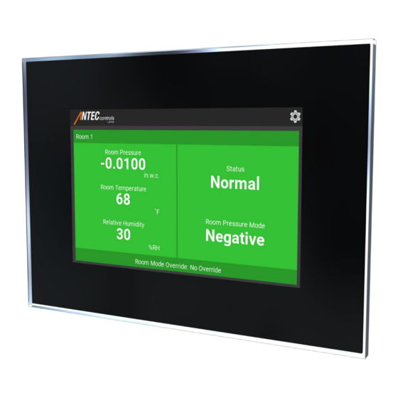
Page 24: Home Screen
MULTI-VARIABLE MONITOR - MANUAL Home Screen Upon start-up of the MVM, the Home Screen is displayed. This Home Screen provides the user with a clear indication of the room mode, status, and pressure reading. Display Description Component Menu Button Opens the navigation menu which allows access to the login screen and the settings menu. -
Page 25: Mvm Operation
MULTI-VARIABLE MONITOR - MANUAL MVM Operation When fully set up, the MVM can be interfaced with any BACnet device to monitor environmental measurements and room status. The MVM will change its display to match the room status of the controller that is being monitored. LCD Display Status Normal –... -
Page 26: Settings
MULTI-VARIABLE MONITOR - MANUAL Settings The Settings are accessible through the Home Screen and are password protected (see Home Screen section). These menus allow the user to change any of the configurable options on the MVM. Display Description Component TCP/IP Allows the user to adjust the IP address of the device when connecting to a local network. - Page 27 MULTI-VARIABLE MONITOR - MANUAL The MVM setup menu is accessible through the touchscreen interface. To enter the setup menu, use the default passcode of 1-6-6-4. NOTE: The passcode is user configurable using the LVIS Configurator software. TCP/IP Configuration Menu Used to configure the TCP/IP settings for the MVM. The menu presents information that allows the user to connect to the MVM.
-
Page 28: Login Screen
MULTI-VARIABLE MONITOR - MANUAL Login Screen The login screen is used to enter passcodes to gain access to locked features. Display Description Component Password Entry Press to enter the assigned passcode. Change Press to change password. Password Current Access Displays current access level. Level Up to 15 levels of access can be assigned. -
Page 29: Configuration
MULTI-VARIABLE MONITOR - MANUAL CONFIGURATION Before Arriving On-Site Before scanning the BACnet network, it is important to determine which devices are being used for the information that will be displayed on the Main Screen. Below is a chart that can be used to map out the necessary information required for the Main Screen. MVM Object BACnet Device BACnet Point Name... -
Page 30: Accessing The Lvis Configurator File Using The Lvis Configurator Software
MULTI-VARIABLE MONITOR - MANUAL Accessing the LVIS Configurator File using the LVIS Configurator Software STEP 1 Open LVIS Configurator. After successfully connecting to the MVM using the Connect to Read Project the MVM through LVIS Configurator section, select from Device STEP 2 Once Read Project from Device... -
Page 31: Accessing The Lvis Configurator File Using A Usb Memory Stick
MULTI-VARIABLE MONITOR - MANUAL Accessing the LVIS Configurator File using a USB Memory Stick STEP 1 Plug USB into one of the two ports on the bottom of the MVM. STEP 2 Enter the settings menu of the MVM by clicking the gear button in the top right corner. - Page 32 MULTI-VARIABLE MONITOR - MANUAL STEP 4 Remove the USB from MVM and insert it into your computer. STEP 5 Open the folder with the project inside and select the file that is labeled as project.lcp STEP 6 Once the project has been opened, reconnect to the MVM. 32 | MVM –...
-
Page 33: Bacnet Network Scanning
MULTI-VARIABLE MONITOR - MANUAL BACnet Network Scanning STEP 1 Plug USB into one of the two ports on the bottom of the MVM. CAUTION Ensure the Device ID, MS/TP Node, and MS/TP Baud Rate have been configured before scanning for BACnet points. Select only an interface option for the physical connections to the MVM. - Page 34 MULTI-VARIABLE MONITOR - MANUAL STEP 4 Discover Devices. Select This will pull in all the devices connected via MS/TP or BACnet IP. CAUTION The list will auto-populate based on what the MVM is able to discover on the BACnet MS/TP or BACnet IP network. If having trouble finding the correct device, please check network settings and wiring.
- Page 35 MULTI-VARIABLE MONITOR - MANUAL STEP 6 Datapoints Select underneath the object that was previously scanned. It will be located in the left-hand bar underneath: BACnet Network Scan (Name of Object Scanned) Datapoints Datapoints NOTE: Once has been selected and highlighted in blue, all associated datapoints will appear in the window to the right.
-
Page 36: Adding Data Points To The Device
MULTI-VARIABLE MONITOR - MANUAL Adding Data Points to the Device STEP 1 Underneath Datapoint Name find the datapoint you would like to Room pull information to the MVM. In this case we are pulling in Pressure Right click the point and select Use on Device STEP 2 Select the clear arrow... - Page 37 MULTI-VARIABLE MONITOR - MANUAL STEP 4 In the datapoint window, select the first datapoint by highlighting it in blue. STEP 5 Select All Properties so it is highlighted in blue. For any Analog Inputs or Outputs (Object types AI or AO): Client Scroll down to the bottom of the properties menu and find Map Type...
-
Page 38: Adding Data Points To The Main Screen
MULTI-VARIABLE MONITOR - MANUAL Adding Data Points to the Main Screen STEP 1 Expand the Templates tab in the left bar of the LVIS Configurator software. CAUTION Do not work in the Root Menu portion of the software, as this may cause display issues that require further configuration. - Page 39 MULTI-VARIABLE MONITOR - MANUAL STEP 4 Select the check box for the desired point. Select Press to add the datapoint to the main screen. STEP 5 The selected datapoint should appear underneath the corresponding name. STEP 6 Data Point In the top bar select the tab.
-
Page 40: Troubleshooting
MULTI-VARIABLE MONITOR - MANUAL TROUBLESHOOTING The following information is provided in the event the MVM does not appear to be functioning normally after installation. Problem Solution 1. BACnet MS/TP is based on a RS-485 network. It must be wired in a daisy chain configuration. - Page 41 Limited Warranty. The complete product catalog can be viewed online at AntecControls.com ® Antec Controls by Price is a registered trademark of Price Industries Limited. © 2019. Printed in Canada. v124...
Need help?
Do you have a question about the Antec controls MVM Series and is the answer not in the manual?
Questions and answers