
Summary of Contents for Vimpex Hydrosense HSCP
- Page 1 Hydrosense HSCP Conventional Water Detection Control Panel Operation and Maintenance Manual Man-1131 Issue 01 November 2009 www.acornfiresecurity.com...
-
Page 2: Table Of Contents
www.acornfiresecurity.com Index Page 1. Introduction........................3 2. Safety and mounting ......................3 3. Technical specification ......................4 4. Control panel fascia......................5 5. Connecting to the circuit board.....................6 6. Software revision number ....................6 7. Wiring to Hydrowire and Hydrosense probes .................7 8. Sounder circuit wiring......................8 9. -
Page 3: Introduction
1. Introduction The HYDROSENSE HSCP range consists of a series of conventional water detection control panels compatible with the Hydrowire system The range consists of 2, 4 and 8 zone control panels. All control panels have an integral, mains powered battery charger and power supply. -
Page 4: Technical Specification
Table 3 - Battery charge voltage versus temperature Temperature Battery charge voltage 29.2 28.56 27.99 27.55 27.13 Table 4 - Compatible sounders Model Type Manufacturer Comments BANSHEE ELECTRONIC VIMPEX WAFER ELECTRONIC VIMPEX FIRECRYER RANGE ELECTRONIC VOICE VIMPEX KOBISHI MOTORISED VIMPEX Man-1131_Hydrosense_HSCP_01 Page 4 of 18 www.acornfiresecurity.com... -
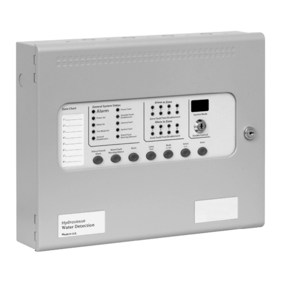
Page 5: Control Panel Fascia
www.acornfiresecurity.com 4. Control panel fascia In addition to standard silence and reset controls, two, seven segment, LED displays and MODE, SELECT and ENTER buttons are provided to allow easy entry and storage of codes to configure the control panel to suit the requirements of the installation. -
Page 6: Connecting To The Circuit Board
The space at the bottom of the enclosure is largely occupied by the standby batteries so this must be borne in mind when considering cable entries. CORRECT INCORRECT INCORRECT 6. Software revision number New features may be added to HYDROSENSE HSCP alarm control C 23 C 22 C 21 C 20 C127... -
Page 7: Wiring To Hydrowire And Hydrosense Probes
Detection zone circuits must be wired as a single, radial circuit with no spurs or T junctions to enable the monitoring circuit to work correctly. Hydrowire connection box K2106 Hydrosense HSCP control panel LAMP Hydrowire cable K2104 or K2105... -
Page 8: Sounder Circuit Wiring
www.acornfiresecurity.com 8. Sounder circuit wiring All sounders must be of the polarised type. If non-polarised sounders are used the control panel will permanently show a fault condition. See table 6 on page 7 for a list of compatible sounder types. Sounder circuits are monitored for open and short circuit faults by placing a 10K end of line monitoring resistor across the last device on the circuit. -
Page 9: Aux 24V Dc Supply
12. Connection to Repeater panels Repeater panels connect via a 2 core cable to the terminals marked RS485 + and – on the HYDROSENSE HSCP main control panel PCB. Up to 7 repeaters may be connected and each repeater has terminals for the incoming cables and outgoing cables. -
Page 10: Connection To Ancillary Boards
13. Connection to Ancillary boards Ancillary boards connect via a 2 core cable to the terminals marked RS485 + and – on the HYDROSENSE HSCP main control panel PCB. Up to 7 Ancillary boards may be connected and each board has terminals for the incoming cables and outgoing cables. -
Page 11: Panel Operation
www.acornfiresecurity.com 14. Panel operation 14.1 Normal condition Under normal conditions, control panels will have only the green, Power On LED lit. 14.2 Alarm condition Upon receipt of an alarm condition by activation of a water detector, the Common Alarm indicator will light and the zonal Alarm indicators will flash at around 2Hz. -
Page 12: Configuration Options
The fault relay can be disabled by selecting configuration option 22. 14.11 Test mode The HYDROSENSE HSCP range of panels enable the system to be tested single handed by using a test mode. When in test mode, activation of a water detector will be automatically reset (after drying the detector) within a few seconds to eliminate the need to return to the control panel to reset after every activation. - Page 13 www.acornfiresecurity.com Table 8 – Configuration codes CODE FUNCTION COMMENTS SOUNDER DELAY TIME = 30 SECONDS Sets the time delay before sounders operate in combination with configuration codes 31 to 48 and access level 2 function AD. SOUNDER DELAY TIME = 1 MINUTE SOUNDER DELAY TIME = 2 MINUTES SOUNDER DELAY TIME = 3 MINUTES SOUNDER DELAY TIME = 4 MINUTES...
-
Page 14: Watchdog Reset Switch
www.acornfiresecurity.com ZONE 1 ANY ALARM DELAYED Zone needs to be triggered for 30 seconds continuously before an alarm is generated. ZONE 2 ANY ALARM DELAYED ZONE 3 ANY ALARM DELAYED ZONE 4 ANY ALARM DELAYED ZONE 5 ANY ALARM DELAYED ZONE 6 ANY ALARM DELAYED ZONE 7 ANY ALARM DELAYED ZONE 8 ANY ALARM DELAYED... -
Page 15: Cpu Fault
www.acornfiresecurity.com 18.3 CPU fault Indicates that the central processor unit has failed to correctly execute code and has been re-started by the system watchdog. The watchdog reset switch must be pressed to clear the CPU fault condition. Press watchdog reset. If system does not return to normal then the panel is probably damaged and needs the circuit board replacing. -
Page 16: Maintenance
The PCB can now be taken out of the panel by removing the 2 holding the plate in position. Fitting the new PCB is the reverse of the procedure for removing the board. 21. Zone designation label All HYDROSENSE HSCP control panels are supplied with a zone designation label onto which zone designations can be written. Man-1131_Hydrosense_HSCP_01 Page 16 of 18 www.acornfiresecurity.com... -
Page 17: Hydrowire Commissioning Details
www.acornfiresecurity.com This enables each zone to be given a text description allowing easier identification of any zones showing an abnormal condition. ZONE DESIGNATION LABEL 22. Hydrowire commissioning details 22.1 Installation 22.1.1 Lengths of Hydrowire should be laid on the floor in the protected area such that the distance between any two Hydrowires is no more than 2 metres. -
Page 18: Remote Lamp Connection
www.acornfiresecurity.com 22.2.2 The + and - terminals inside the connection box must be connected to the Z+ and Z terminals at the control panel. 22.2.3 The end of line resistors at the control panel should be discarded. 22.2.4 It is advisable to leave off the lid of the connection box, until all testing is complete. 22.3 Remote Lamp Connection 22.3.1 In some installations, particularly in floor voids, it is desirable to identify the area in which water has been detected, with a remote indicator unit mounted above the void.
Need help?
Do you have a question about the Hydrosense HSCP and is the answer not in the manual?
Questions and answers