
Related Manuals for Foxcroft FX-CL-F

Summary of Contents for Foxcroft FX-CL-F
- Page 1 Model FX-CL-F/T Reagentless Amperometric Free or Total Chlorine Residual Analyzer Instruction Manual Document No. OMFXCLFT042018.1 2018 Foxcroft Equipment & Service Co. Inc.
-
Page 3: Table Of Contents
2.3 Sensor Conditioning 2.4 Cleaning The Electrode Finger Tip 2.5 Sensor Maintenance, Storage Section 3 System Component Identification & Description 3.0 Model FX-CL-F/T Specifications 3.1 Analyzer Component Identification & Description 3.2 Main Circuit Board Component Identification Section 4 Installation 4.1 Sample Point Selection Guidelines 4.2 Unpacking... - Page 4 Table of Contents 7.6 Configuring the Alarm Relays 7.7 Calibration 7.71 Setting the Zero Point 7.72 Calibrating the Span (Standard) 7.81 Settings Submenu Screen 7.82 Screen Settings Section 8 Troubleshooting 8.1 Specific Troubleshooting Of The Sensor 8.11Testing the leak-tightness of the membrane cap 8.12 Testing the sensor electronics (dry run) 8.13 Testing the zero point Section 9 Maintenance...
-
Page 5: Section1 General Information
Every effort has been made to ensure the accuracy of this document at the time of printing. In accuracy of this document at the time of printing. In accordance with the company’s policy of continuous product improvement, Foxcroft reserves the right accordance with the company’s policy of continuous product improvement, Foxcroft reserves the right accordance with the company’s policy of continuous product improvement, Foxcroft reserves the right... -
Page 6: System Description, Limitations
The measurement system does not alter the sample and does not add chemicals to the sample stream. The model FX-CL-F/T is intended to sample process water that has been treated to US EPA National Secondary Drinking Water Standards or swimming pool quality standards only. -
Page 7: Sensor Precautions
Section 1.4 Sensor Precautions You must read and follow the sensor precautions before attempting to start up the analyzer to prevent damage to the sensor. NOTE: Using the sensor without mounting it in the supplied flow cell will lead to incorrect measurement results;... -
Page 8: Total Chlorine Sensor Description & Operation
Section 1.4 Sensor Precautions Sensors are intended for clean drinking or industrial process water applications only, with quality similar to drinking and swimming pool water. Consider “Clean water” as being filtered and treated to US EPA National Secondary Drinking Water Standards as follows: Contaminant Secondary MCL Aluminum... -
Page 9: 3-Electrode Free Chlorine Sensor Description & Operation
Section 1.6 Free Chlorine Sensor Description 2 & 3-Electrode Free Chlorine Sensor Description The 2 or 3-electrode membrane-covered, amperometric sensors are used to measure the concentration of free chlorine in drinking and swimming pool water, industrial, process and cooling water. The following inorganic chlorinating agents can be measured with the sensor for free chlorine: chlorine gas (Cl2), electrolytically generated chlorine, sodium hypochlorite (NaOCl, chlorine bleach lye), calcium hypochlorite (Ca(OCl)2) or chlorinated lime (Ca(OCl)Cl). -
Page 10: 2-Electrode Free Chlorine Sensor Description & Operation
Section 1.6 Free Chlorine Sensor Description 3-Electrode Free Chlorine Sensor As there must be an electrical connection between the counter electrode and the measurement medium, the measurement medium must have a minimum conductivity of approx. 10 µ S/cm. This means that the sensors are not suitable for use in highly-purified water, or similar. 2-Electrode Free Chlorine Sensor Description The sensor for free chlorine is a potentiostatic 2-electrode sensor with a micro porous, Hydrophobic (moisture repellent) PTFE membrane and special electrolyte. -
Page 11: Assembly Diagram, 3-Electrode Sensors
Section 1.8 Assembly Diagram, 3-Electrode Sensors Details Total Chlorine Sensor and 3-Electrode Free Chlorine Sensor (14) (10) (13) (11) (12) Cable gland nut Terminal Cover O-ring 2-pin terminal for measuring cable connection Electrode shaft with integrated electronics Counter electrode (stainless steel) O-ring Electrode finger (reference electrode) Measurement electrode... -
Page 12: Assembly Diagram, 2-Electrode Sensor
Section 1.9 Assembly Diagram, 2-Electrode Sensor Details 2-Electrode Free Chlorine Sensor (12) (11) (10) Cable gland nut Terminal Cover O-ring 2-pin terminal for measuring cable connection Electrode shaft with integrated electronics O-ring Electrode finger (reference electrode) Measurement electrode Transparent vent seal (10) Membrane cap (11) PTFE membrane (12) Vent hole... -
Page 13: Specifications, Total Chlorine Sensor
Section 1.10 Specifications, Total Chlorine Sensor Specifications, Total Chlorine Sensor Analyte Total chlorine Membrane type Hydrophilic membrane 2-pin terminal, polyamide PG7 screw connection; Measuring cable wire cross section 2x 0.25mm 2 , cable diameter approx. 4 mm connection Voltage supply U B 12 to 30 V DC (electrical isolation recommended) Electromagnetic According to EN 61326-1... -
Page 14: Specifications, Free Chlorine Sensors
Section 1.11 Specifications, Free Chlorine Sensors Free Chlorine Sensor Data, 2 -Electrode & 3-Electrode with Reduced pH Dependence Analyte Free chlorine, 2-electrode Free chlorine, 3-electrode reduced pH dependence Membrane type Hydrophobic PTFE membrane Hydrophilic membrane 2-pin terminal, polyamide PG7 screw connection; Measuring cable wire cross section 2x 0.25mm 2 , cable diameter approx. -
Page 15: Flow Cell Assembly
Section 1.12 Flow Cell Assembly The flow cell (part no. 303500) is fastened to a wall or mounting panel with mounting bracket (part no. 303501) Sensor Mounting bracket (303501) Connection G1/4 for hose ø 8mm x 6mm Flow cell housing Removable inspection glass... -
Page 16: Sensor & Flow Cell Assembly
Section 1.13 Sensor & Flow Cell Assembly Overview (10) Sensor Inspection glass Union nut Inlet G1/4A or DN10 Flow Cell Stepped collar 1" Outlet G1/4A or DN10 Compression ring (10) O-ring, stepped O-ring, inspection glass collar Part of the flow cell. Caution: When assembling and installing the sensor (1) make certain the O- rings and threads are clean and undamaged The transparent inspection glass (6) can be unscrewed from the fitting housing for cleaning. -
Page 17: Membrane Cap Removal, Filling With Electrolyte
Section 2.0 Membrane Cap Removal, Filling With Electrolyte Screwing the membrane cap off and on CAUTION: The electrolyte will come out of the valve opening when the membrane cap is screwed on. Wear safety goggles and gloves. Wash off electrolyte (an aqueous solution of an alkali halide) under flowing water. CAUTION: - NEVER SCREW THE MEMBRANE CAP ON OR OFF WITHOUT FIRST MOVING THE VENT SEAL AWAY FROM THE VENT HOLE. - Page 18 Section 2.0 Membrane Cap Removal, Filling With Electrolyte Filling membrane cap with electrolyte 5. To avoid forming bubbles do not shake the electrolyte. Make sure the vent hole is open. Tilt the electrolyte bottle as shown to minimize bubbles and fill the membrane cap up to the brim with electrolyte, if needed tap to eliminate bubbles.
-
Page 19: Assemble The Sensor
Section 2.1 Assemble the Sensor 7. After tightening the membrane cap, slide the vent seal up into the groove, so that it covers the vent hole. Rub around the vent seal to remove any bubbles or voids. If liquid leaks through the membrane, the membrane is faulty and you must use a new membrane cap. -
Page 20: Sensor Installation
Section 2.2 Sensor Installation Install the Sensor 12. Insert the sensor into the flow cell with the wiring terminals facing you. Slide the union nut over the sensor and tighten onto the flow cell. 13. Slide the cable gland nut and terminal cover over the sensor cable in the order shown. -
Page 21: Sensor Conditioning
Section 2.3 Sensor Conditioning Assemble the Sensor 15. Screw the terminal cover onto the sensor and then tighten the cable gland nut. 16. The solution ground pin on the front of the flow cell is normally not needed, it may be used if you find a solution ground is necessary. Sensor Conditioning Time The sensor will not provide a constant value until after a conditioning time of 2 hours has passed. -
Page 22: Cleaning The Electrode Finger Tip
Section 2.4 Cleaning The Electrode Finger Tip CAUTION: Potential damage to the sensor Cleaning the electrode finger (3,4) incorrectly may damage the sensor. Do not sand the brown coating on the combined counter and reference electrode (3). • Do not touch or contaminate the electrode finger (3,4). •... -
Page 23: Sensor Maintenance, Storage
Section 2.5 Sensor Maintenance, Storage Note: The service life of the electrolyte is 3 to 6 months. The service life of the membrane depends on the water quality. If the sensor still indicates values that are too low after the electrode finger tip has been cleaned, a new membrane cap must be used. -
Page 24: Model Fx-Cl-F/T Specifications
Section 3.0 Model FX-CL-F/T Specifications General Product Description Amperometric reagentless total chlorine residual analyzer Intended Use Continuous monitoring and control of chlorine residual prior to dechlorination Measurement Method Amperometric potentiostatic membrane covered 3-electrode Parameters Measured Total (combined) residual chlorine Available Operating Ranges 0-0.5 mg/l to 0-20 mg/l (ppm) -
Page 25: Analyzer Component Identification & Description
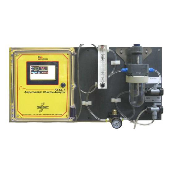
Section 3.1 Analyzer Component Identification & Description Reagentless Chlorine Analyzer on Flow Panel Sample inlet, 2-way ball valve Flow Cell Sensor Flow meter with valve, 12 GPH Pressure regulator with gauge Drain tubing Sample tap tubing Analyzer electronics 5 Amp fused power input module 24VDC power supply, 88-264 Volts AC, 50/60 Hz. -
Page 26: Main Circuit Board Component Identification
3.2 Main Circuit Board Component Identification Component Identification Touch screen display connection screen display connection Chlorine sensor connection mA output (only one output is output is active) Power input module Power supply (under main circuit board Power supply (under main circuit board, not shown, see previous page) 1Amp Hi &... -
Page 27: Section 4 Installation
Section 4 Installation 4.1 Sample Point Selection Guidelines General Considerations The sample must be taken at a point after the chlorine has been thoroughly mixed and has had time to react completely with the process water. A sample point that is too close to the chorine injection point will deliver a sample that is not mixed adequately or has not had sufficient time to complete the chemical reaction, thereby producing inaccurate readings. -
Page 28: Unpacking
2.3 Serial Number & Software Version Number The FX-CL-F/T chlorine analyzer is shipped with two serial number labels found on the bottom right side of the enclosure, and on the inside of the enclosure door. The labels include the factory calibrated chlorine residual range. -
Page 29: Wall Mounting, Plumbing
Section 4.5 Wall Mounting, Plumbing Wall mounting the analyzer Locate at approximate shoulder height for convenience. The FX-CL-F/T should be level from side to side and front to back. 1. Attach the four mounting feet to the rear of the electronics enclosure using the included 5/16"- 18 x 1/2"... -
Page 30: Section 5 Electrical Installation
5.2 Power Connection The FX-CL-F/T chlorine analyzer uses a universal switching power supply and can be connected to chlorine analyzer uses a universal switching power supply and can be connected to chlorine analyzer uses a universal switching power supply and can be connected to 100-260 Volts AC, 50/60 Hz. -
Page 31: Circuit Board Layout And Identification
Section 5 Electrical Installation 5.3 Circuit Board Layout and Identification 1A Relays NO / NC, with LED circled Processor "heartbeat" flashing LED indicator pH input Program / Run switch, factory use only Temperature input Programming input connector, factory use only 4-20mA outputs, 1 active Reset switch, factory use only Jumper, Free / Total chlorine sensor,... -
Page 32: Factory Default Wiring
Section 5.4 Factory Default Wiring 5.41Chlorine Sensor Input TB9 +24 Blue with white dots or Black TB9 1 White with blue dots or White Shield (clear) TB9 COM 5.42 Display Wiring Blue (-) TB2-4 White Blue Dots TB2-3 White Red Dots TB2-2 Orange (+) TB2-1... -
Page 33: Current Output Wiring
5.4 Factory Default Wiring 5.44 Current Output Wiring Disinfectant (+) TB11-1 Disinfectant (-) TB11-5 pH (+) TB11-2 pH (-) TB11-6 Temperature (+) TB11-3 Temperature (-) TB11-7 Spare (+ ) TB11-4 Spare (-) TB11-8 CAUTION: MUST CONNECT TO AN ISOLATED INPUT TO AVOID GROUND LOOPS WHICH CAN DISRUPT THE MEASURING ELECTRODE. DO NOT APPLY POWER TO THIS mA OUTPUT. -
Page 34: Section 6 Startup
Turn on the analyzer by pressing the off/on rocker switch located on the bottom right underside surface of the analyzer enclosure. The Foxcroft gray splash screen will appear as the software boots up, followed by the Home operating screen. On the circuit board the heartbeat indicator below the processor will be flashing red, and the “Power On”... - Page 35 6 Startup Section Startup (continued) Allow the sensor to run for at least 1-2 hours (depending on sensor type) to become conditioned to the process. Valid readings are not possible until the sensor has become conditioned. Calibrate the chlorine sensor span (standard) using the concentration determined by a grab sample analysis using an approved method.
-
Page 36: Section 7 Touch Screen Interface & Navigation
Section 7 Touch Screen Interface & Navigation 7.1 Main Screen Identification and Description The main screen is both the home and run screen that will display automatically after the start up routine has completed and while the analyzer is in operation. Navigation through the menus is done simply by touching the item of interest. -
Page 37: Menu Structure
Section 7.2 Menu Structure MAIN RANGE ALARMS CALIBRATION SETTINGS pH Mode Span Set High Alarm Set Low Alarm Set Chlorine Zero Screen Settings Man/Auto Low Alarm Screen High Alarm Chlorine Delay Standard Delay Brightness Volume... -
Page 38: Screen Navigation
Section 5 Touch Screen Interface & Navigation 7.3 Screen Navigation Navigation through the menus is done simply by touching the item of interest. After performing an adjustment you will return to the main home screen by touching menu. You will find that lightly tapping with your fingernail works the best. -
Page 39: Configuring The Operating Range & Ma Output
Section 7 Touch Screen Interface & Navigation 7.4 Configuring the Operating Range & mA Output Setting the operating range will automatically set the mA output of the disinfectant residual to match the operating range, set the high alarm to 90% of span, and low alarm to 10% of span. The alarms can later be configured as needed. -
Page 40: Configuring The Alarm Relays
Section 7 Touch Screen Interface & Navigation 7.6 Configuring the Alarm Relays There are a total of (8) 1A dry contact form C relays each with LED indicator installed on the circuit board, only (3) are active in the standard configuration. Relay 1 is dedicated to the High disinfectant alarm, Relay 2 for the Low disinfectant alarm, and Relay 3 for the No Flow alarm. -
Page 41: Calibration
The accuracy of the FX-CL-F/T can never be greater than the instrument it is being calibrated against. Accuracy is a function of the method used, inherent tolerances in the calibration instrument, the quality and freshness of reagents, and the care taken to perform the calibration. -
Page 42: Setting The Zero Point
Section 7.7 Calibration 7.71 Setting the Zero Point. A zero-point calibration is not required for the chlorine sensors included. If there is no chlorine present in the process medium, approximately zero is indicated. The zero point is independent of changes in the flow rate, conductivity, temperature and pH value. If needed, the zero point can be re-set electrically. -
Page 43: Settings Submenu Screen
Section 7.8 Settings Submenu Screen 7.81Settings Screen The settings screen allows you to adjust pump motor speed (on vinegar buffered systems only) as well as the screen brightness and audio volume. This screen also contains the serial number, the software version number, and display version number. These numbers are required for customer service and technical support. -
Page 44: Section 8 Troubleshooting
Section 8 Troubleshooting Error/fault Possible cause Remedy Preventive measures Output signal of the sensor is Incorrect calibration Repeat calibration Calibrate the sensor more too low or too high according frequently if required Sensor output signal is too Settling time too short. Wait at least 2 hours low. -
Page 45: Specific Troubleshooting Of The Sensor
Section 8 Troubleshooting Error/fault Possible cause Remedy Preventive measures Sensor is unusually slow in The membrane is partially Replace membrane cap. Take steps to improve the responding blocked by pollutants water quality. such as calcium or oil. Disinfectant is prevented from reaching the sensor Output signal of the sensor The sensor has been... -
Page 46: Testing The Sensor Electronics (Dry Run)
Section 8.1 Specific troubleshooting on the sensor 8.12 Testing the sensor electronics (dry run) 1. Unscrew the membrane cap per procedures. 2. Carefully rinse the electrode finger and dry it carefully with a clean cloth. 3. Connect the sensor to the indicator/controller and wait for approx. 5 minutes. 4. -
Page 47: Section 9 Maintenance
Section 9 Maintenance The FX-CL-F/T analyzer is designed to operate continuously, 24 hours a day, 365 days a year. The system requires little routine maintenance other than changing the sensor electrolyte at prescribed intervals and mandated calibration checks. However, regular maintenance should be performed to ensure optimum performance and accuracy. -
Page 48: Section 10 Parts List
Section 10 Parts List Description Part No. Touch Screen Display 400001 Display Cable 400002 Circuit Board 400003 Power Supply 400004 Power Cable 400005 6A fuse, power entry module 400008 Flow cell, single sensor 303500 Wall mount bracket, Stainless Steel, for single sensor flow cell 303515 Additional tubing flexible PVC, per foot 303526... -
Page 49: Section 11 Service Contact, Return Policy
A Return Material Authorization Number (RMA) is required before shipping any products for service. Call telephone number above to receive a RMA number. NOTE: Returns will only be held at Foxcroft for 90 days. If a decision is not made regarding the repair, the product will be returned. -
Page 50: Section 12 Product Warranty
Buyer agrees to hold Foxcroft Equipment & Service harmless from all claims for damages arising out of injury or death to any person or damage to any facility, or any other property, or loss of use of any... - Page 52 Serial Number Label for FX-CL Amperometric Chlorine Residual Analyzer Foxcroft Equipment & Service Co. Inc. 2101 Creek Road, P .O. Box 39 Glenmoore, PA 19343 Tel: (800) 874-0590 (610) 942-2888 Fax: (610) 942-2769 Email: service@foxcroft.com www.foxcroft.com...
Need help?
Do you have a question about the FX-CL-F and is the answer not in the manual?
Questions and answers