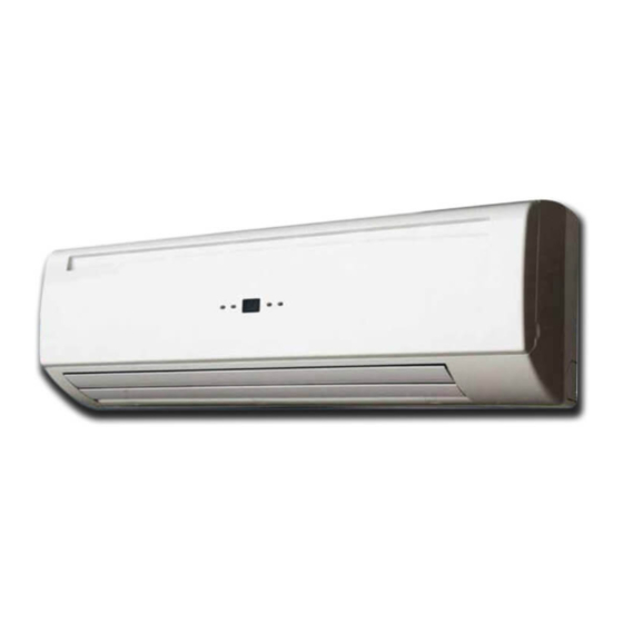
Summary of Contents for Surna ISOSTREAM SWFC
- Page 1 ISOSTREAM ® SURNA WALL FAN COIL OPERATING AND MAINTENANCE MANUAL Model: SWFC August 2021 s u r n a . c o m...
-
Page 2: Table Of Contents
INVESTING IN QUALITY, RELIABILITY & PERFORMANCE World Leading Design and Technology ISO 9001 QUALITY Every product is manufactured to meet the stringent requirements of the internationally recognized ISO 9001 standard for quality assurance in design, development and TABLE OF CONTENTS production. -
Page 3: Specifications
Connections 1/2 (12.7) NPT capacities. Condensate Drainage 5/8 (16) NPT Connection in (mm) 34-1/2 (876) 41-7/8 (1063) SWFC Surna Wall Fan Coil Dimensions 9 (228) 9-7/16 (240) 11-13/16 (300) 1 (25.4) Net Weight lbs (kg) 24.3 (11) 30.9 (14) 35.3 (16) - Page 4 SOUND DATA DIMENSIONAL DRAWINGS OF SWFC-4/18 Model SWFC-4 SWFC-18 SWFC-30 Speed H(700) M(600) L(500) H(1300) M(1100) L(900) H(1350) M(1200) L(900) Sound Power 39.4 36.2 36.2 60.0 54.5 47.5 60.3 56.9 49.4 dB(A) 20.0 Hz 23.7 20.1 16.5 14.7 23.8 19.0 20.8 19.9 17.0...
-
Page 5: Technical Description
TECHNICAL DIMENSIONAL DRAWINGS OF SWFC-30 DESCRIPTION Cover Coil Figure 2: SWFC-30 dimensional drawings Base Control Box Valve Unit Dimensions in (mm) Model Motor + fan blower Figure 3: SWFC unit overveiw SWFC-30 3-9/16 41-5/16 3-9/16 9/16 2-7/8 2-15/16 (90) (1050) (51) (90) (15) -
Page 6: Warnings
Consult with an electrician before attempting electrical installation. Using Surna wall fan coils in a manner not described in this manual may void its warranty and any safeties provided herein. -
Page 7: Warranty Information
Dealer or Customer; (b) re-installation the Surna wall fan coil. Doing so presents an electric costs of repaired equipment; (c) re-installation costs of Exclusions from this Warranty include damage or failure replacement equipment;... -
Page 8: Installation Instructions
INSTALLATION INSTRUCTIONS WIRING DIAGRAM Wiring Diagrams SWFC (SWC) - S CONTROL SWFC CONTROL SPECIFICATIONS - COMPLETE FUNCTION (S) MECHANICAL WIRING WARNING: Turn off the breaker until all electrical This wall fan coil unit is designed to be mounted in a connections are made. - Page 9 CONTROL SPECIFICATIONS I/O Port Code 2-Pipe Analog Input Chilled water sensor Coil sensor (Ti1) High speed Medium speed 24VAC input signals from wired thermostat Low speed Power Input EH signal Phase Neutral 220V/1Ph/60Hz SWFC CONTROL SPECIFICATIONS - FLE XIBLE FUNCTION PCB (W) Earth Signal Input 0-10VDC...
- Page 10 CONTROL LOGIC SPECIFICATION UNIT INSTALLATION ELECTRICAL HEATER OPERATION POWER ON SETTING Pass the piping through the hole in the wall and hook the indoor unit on the mounting plate by the upper hooks. After unit is turned ON, EH relay will be ON when EH When any fan speed is selected or the modulating 2.
- Page 11 VALVE CONNECTION DRAIN PUMP AND INSTALLATION FIXTURE (OPTIONAL) Upon request, the metal bracket for fixing the drain pump and drain pump kits can be offered. Please consult our PRE-ASSEMBLY sales representatives for these optional accessories. Figure 8: Drain pump kits (optional) Flexible hose Valve body 1/2in...
- Page 12 AIR VENT AND WATER PURGE VALVES OPERATING LIMITS Power Supplies After connecting the water inlet and outlet pipes to the main supply lines turn on the main breaker and operate Volt Phase Model the unit in COOLING mode. The high-wall unit should be mounted on a solid wall. 208-240 SWFC 2.
-
Page 13: Routine Maintenance
2. Drill a 65mm diameter hole with a descending slope. 3. Seal it off with putty after installation. Table 10: Routine maintenance CONTACT US Contact Surna via email at support@surna.com or via phone at 303.993.5271. Figure 13: Condensate drainage hole drilling... -
Page 14: Troubleshooting
TROUBLESHOOTING OPENING AND CLOSING OF LIFT-UP GRILLE COVER Open the grille cover by lifting from the bottom position indicated by the arrows. 2. Close the grille cover by pressing down at the positions indicated by the arrows. FRONT COVER ASSEMBLY REMOVAL Set the horizontal louver to the horizontal position. - Page 15 303.993.5271 info@surna.com All data subject to change without notice s u r n a . c o m...

Need help?
Do you have a question about the ISOSTREAM SWFC and is the answer not in the manual?
Questions and answers