Table of Contents
Advertisement
Quick Links
Advertisement
Table of Contents

Summary of Contents for WinSystems ITX-M-CC452-T10
- Page 1 ITX-M-CC452-T10 Industrial Mini-ITX Carrier Reference Board for COM Express Type 10 Module with Dual Ethernet, NVMe, and PCIe Expansion Product Manual WINSYSTEMS, Inc. | 2890 112th Street, Grand Prairie, Texas 75050 | 817-274-7553 | info@winsystems.com | www.winsystems.com...
- Page 2 Copyright 2021, WINSYSTEMS, Inc. No part of this document may be copied or reproduced in any form or by any means without the prior written consent of WINSYSTEMS, Inc. The information in the document is subject to change without notice. The information furnished by WINSYSTEMS, Inc.
-
Page 3: Table Of Contents
ITX-M-CC452-T10 Table of Contents Before You Begin........... 5 1.1 Warnings . - Page 4 ITX-M-CC452-T10 6.5.13 J9 - SATA 3 (6 Gbps) ..........19 6.5.14 J27 - microSD.
-
Page 5: Before You Begin
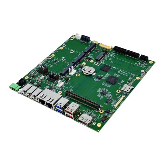
ITX-M-CC452-T10. Functionality The ITX-M-CC452-T10 is an industrial Mini-ITX small form factor Type 10 reference carrier board designed to fully test WINSYSTEMS’ COMeT10- 3900 COM Express Type 10 Mini module. The carrier board adheres to the PICMG COM Express specifications providing compatibility with other COM Express mini type 10 modules. -
Page 6: Features
Ethernet • 1x Gigabit Intel i210 Ethernet port from COM module • 1x Gigabit Intel i210 from PCIe switch onboard ITX-M-CC452-T10 • Wake-on-LAN support, both channels Storage • M.2 M-key 2280 with support for PCIe x4 NVMe •... - Page 7 ITX-M-CC452-T10/Features On-Board I/O Supported from Type Provided by ITX-M-CC452-T10 10 Module 2x TTL serial ports • 2x RS232 serial ports (3-wire) provided by onboard RS232 transcievers LPC bus • 2x RS232/422/485 serial ports (4-wire) provided by multi-protocol transcievers 5x USB 2.0 and •...
-
Page 8: System Block Diagram
(one with mSATA support), M.2 M-key 2280 with support for PCIe x4 NVMe SSD drives, and a SATA port for external SSDs. The ITX-M-CC452-T10 is a fully production ready platform and is a versatile and easily configured solution with customizable COM module, storage, and I/O options to suit the industrial use case. -
Page 9: Specifications
ITX-M-CC452-T10/Specifications Specifications The ITX-M-CC452-T10 adheres to the following specifications and requirements. Feature Specification Electrical Wide range DC input: 9 V to 20 V Models ITX-M-CC452-T10-m-t m = Module installed (0 = no module is default) t = Thermal solution installed (0 = no thermal solution... -
Page 10: Configuration
ITX-M-CC452-T10/Configuration Configuration This section describes the ITX-M-CC452-T10 components and configuration. Component Layout 6.1.1 Top and Side View 2x RS232/ SATA PWR (J8) SATA (J9) USB Touchscreen LVDS (J15) 2x RS232 GPIO (J26) 422/485 (J22) (J12) (J23) LVDS Configuration Jumpers (JP3) Mini PCIe #3 M.2 2280... - Page 11 ITX-M-CC452-T10/Configuration Item Description Reference Power Power input page 15 Power input header page 16 CMOS battery input page 16 Internal coin cell battery page 17 SATA power output page 18 External fan power output page 18 Power button page 19...
-
Page 12: Configuration And Installation
ITX-M-CC452-T10/Configuration Configuration and Installation When installing a Type 10 COM module onto a compatible COM Express Type 10 carrier board, follow the instructions below to ensure that there is no damage to the COM module or the carrier board. Avoid Electrostatic Discharge (ESD) Only handle the circuit board and other bare electronics when electrostatic discharge (ESD) protection is in place. -
Page 13: Jumpers
ITX-M-CC452-T10/Configuration Jumpers 6.3.1 JP1 - SDP Interface Header The ITX-M-CC452-T10 has four software-defined pins (SDPs) that can be used for IEEE1588 auxiliary device connections, enable/disable of the device, and for other miscellaneous hardware or software-control purposes. Layout and Pin Reference... -
Page 14: Jp3 - Lvds Configuration Jumpers
ITX-M-CC452-T10/Configuration 6.3.3 JP3 - LVDS Configuration Jumpers NOTE Do NOT install jumpers 1 - 2 and 3 - 4 at the same time. NOTE Do NOT install jumpers 7 - 8 and 9 - 10 at the same time. Layout and Pin Reference... -
Page 15: Led Indicators
Connectors 6.5.1 J3 - Power Input Use this connection to supply power to the ITX-M-CC452-T10. This computer supports a wide range DC input power from 9 V to 20 V. NOTE Do not plug power into J3 and J7 at the same time. -
Page 16: J7 - Power Input Header
Part Number: 1827703 6.5.2 J7 - Power Input Header Use this connection to supply power to the ITX-M-CC452-T10. This computer supports a wide range DC input power from 9 V to 20 V. NOTE Do not plug power into J3 and J7 at the same time. -
Page 17: B1 - Internal Coin Cell Battery
Part Number: DF13C-2S-1.25C 6.5.4 B1 - Internal Coin Cell Battery The ITX-M-CC452-T10 accepts an external battery at J17 or an internal coin cell battery at B1. Battery input is configured using jumper JP2. See “JP2 - Battery Select Jumper” on page 13. -
Page 18: J8 - Sata Power Output
ITX-M-CC452-T10/Configuration 6.5.5 J8 - SATA Power Output Power is supplied to the SATA device via the connector at J8. Layout and Pin Reference Name Name +5 V +12 V Connector • Hirose DF11 series 2.00 mm dual-row 4-pin Part Number: DF11C-4DP-2V(57) Matching Connector •... -
Page 19: Sw3 - Power Button
ITX-M-CC452-T10/Configuration 6.5.7 SW3 - Power Button The ITX-M-CC452-T10 turns on automatically when power is applied to the computer and does not require the power button to be pressed. The power button connector can be used to wake the computer after shutdown, sleep, or system standby if power is not removed. -
Page 20: J27 - Microsd
ITX-M-CC452-T10/Configuration 6.5.14 J27 - microSD The ITX-M-CC452-T10 provides a microSD card socket for loading an operating system or for additional storage. The microSD signals are muxed with the GPIO. 6.5.15 J25 - DisplayPort Standard full-size 20-pin DisplayPort (Version 1.2). v1.0 www.winsystems.com... -
Page 21: J20 - Embedded Displayport (Edp)
ITX-M-CC452-T10/Configuration 6.5.16 J20 - Embedded DisplayPort (eDP) The ITX-M-CC452-T10 supports one embedded DisplayPort (eDP) interface. The eDP and LVDS interfaces cannot be used at the same time. The COMeT10-3900 or equivalent Type 10 COM module dictates which interface is being used. -
Page 22: J15 - Lvds And Backlight
ITX-M-CC452-T10/Configuration 6.5.17 J15 - LVDS and Backlight The ITX-M-CC452-T10 supports one single channel LVDS interface. The eDP and LVDS interfaces cannot be used at the same time. The COMeT10-3900 or equivalent Type 10 COM module dictates which interface is being used. -
Page 23: J10, J11, J13 - Audio I/O
ITX-M-CC452-T10/Configuration 6.5.18 J10, J11, J13 - Audio I/O Three 1/8th in. (3.5 mm) HD audio jacks are provided. The Type 10 module supports HD audio signals to the ITX-M-CC452-T10, which provides a Realtek ALC888S-VD HD audio codec. Audio Connectors Number... -
Page 24: J19 - Com Express Type 10 Mini Module Interface Connector
ITX-M-CC452-T10/Configuration 6.5.20 J19 - COM Express Type 10 mini Module Interface Connector Layout and Pin Reference Row A Description Description Description GND(FIXED) USB_6_7_OC# LVDS_A2+ GBE0_MDI3- USB4- LVDS_A2- GBE0_MDI3+ USB4+ LVDS_VDD_EN GBE0_LINK100# GND(FIXED) LVDS_A3+ GBE0_LINK1000# USB2- LVDS_A3- GBE0_MDI2- USB2+ GND(FIXED) GBE0_MDI2+... - Page 25 ITX-M-CC452-T10/Configuration Layout and Pin Reference Row B Description Description Description GND(FIXED) USB_4_5_OC# DDI0_PAIR2+ GBE0_ACT# USB5- DDI0_PAIR2- LPC_FRAME# USB5+ DDI0_PAIR4+ LPC_AD0 GND(FIXED) DDI0_PAIR4- LPC_AD1 USB3- LVDS_BKLT_EN LPC_AD2 USB3+ GND(FIXED) LPC_AD3 USB_0_1_OC# DDI0_PAIR3+ LPC_DRQ0# USB1- DDI0_PAIR3- LPC_DRQ1# USB1+ LVDS_BKLT_CTRL LPC_CLK EXCD1_PERST# VCC_5V_SBY...
-
Page 26: J14 - Ethernet (Rj45) 1 And 2
1 A maximum continuous current and 5 Gbps transfer speed. 6.5.23 J24 - USB 2.0 Type-A The Type 10 module supports five USB 2.0 ports to the ITX-M-CC452-T10, which provides two USB 2.0 ports to J24 and three USB 2.0 ports to each Mini-Card #1-3. -
Page 27: J23 - Serial Rs232 Ports 1 And 2 (3-Wire)
ITX-M-CC452-T10/Configuration 6.5.25 J23 - Serial RS232 Ports 1 and 2 (3-wire) The Type 10 module supports two TTL serial ports to the ITX-M-CC452-T10, which provides two RS232 serial ports (3-wire port consisting of TX/RX and GND) via on-board RS232 transceivers. -
Page 28: J26 - Gpio
Molex Milli-Grid receptacles with center polarization key and locking ramps Part Number: 51110-2051 6.5.27 J26 - GPIO The Type 10 module supports GPIO signals to the ITX-M-CC452-T10, which provides 4x general purpose inputs and 4x general purpose outputs. Layout and Pin Reference Diagram... -
Page 29: J4 - Mini Pcie #1 Connector
ITX-M-CC452-T10/Accessories and Cables 6.5.28 J4 - Mini PCIe #1 Connector The ITX-M-CC452-T10 Mini PCIe socket supports a variety of peripherals as available in this format. Though the sockets support other devices, they are most often used to add WiFi or 3G/LTE modem support. This Mini PCIe socket supports PCIe, and USB 2.0. - Page 30 ITX-M-CC452-T10/Accessories and Cables Standoff kits are available and recommended for use with the ITX-M- CC452-T10. The following table lists the items contained in each kit. Component Description KIT-PCM-STANDOFF-4 Standoff Nylon 0.25” hex, 0.600” long male/female 4-40 4 4 pc. nylon hex PC/104...
-
Page 31: Best Practices
The ITX-M-CC452-T10 requires 5 V to 20 V to operate. Verify the power connections. Incorrect voltages can cause catastrophic damage. The ITX-M-CC452-T10 has two power connectors at J3 and J7. A single 5 V to 20 V DC input and ground is required to power the board. - Page 32 Mounting and Protecting the I/O Module To avoid damage, mount the ITX-M-CC452-T10 properly. Standoff kits are available and recommended for use with the ITX-M-CC452-T10. See the table on page 29 for the items contained in each kit.
- Page 33 ITX-M-CC452-T10/Best Practices Do not bend or flex the ITX-M-CC452-T10—Bending or flexing can cause irreparable damage. Embedded computer modules are especially sensitive to flexing or bending around ball grid array (BGA) devices. BGA devices are extremely rigid by design, and flexing or bending the embedded computer module can cause the BGA to tear away from the printed circuit board.
- Page 34 ITX-M-CC452-T10/Best Practices Conformal Coating Applying conformal coating to a WINSYSTEMS product does not in itself void the product warranty, if it is properly removed prior to return. Coating can change thermal characteristics and impedes our ability to test, diagnose, and repair products. Any coated product sent to WINSYSTEMS for repair will be returned at customer expense and no service will be performed.
-
Page 35: Mechanical Drawings
ITX-M-CC452-T10/Mechanical Drawings Appendix B. Mechanical Drawings ITX-M-CC452-T10 Mechanical Drawing v1.0 www.winsystems.com Page 35... -
Page 36: Warranty Information
Customer for the purchase of Products or licensing of Software hereunder. In the event this Order is placed in the hands of an attorney or collection agency by WINSYSTEMS to collect any sums due hereunder to WINSYSTEMS, Customer shall pay all reasonable attorney's fees, expenses, collection and court costs incurred by WINSYSTEMS.
Need help?
Do you have a question about the ITX-M-CC452-T10 and is the answer not in the manual?
Questions and answers