Table of Contents
Advertisement
Available languages
Available languages
Advertisement
Chapters
Table of Contents

Subscribe to Our Youtube Channel
Related Manuals for Mega SSC Series


Summary of Contents for Mega SSC Series
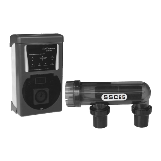
- Page 1 SSC SERIES SALT CHLORINATOR USER MANUAL S S C 2 5 MESW13061409...
-
Page 2: Table Of Contents
CONTENT 1.Working Principle............. 2.Product picture..............3.Dimension................ 4.Working condition............. 5.Product specification............6.Product Features........... 7.Installation Guide........... Installation......................9.Operation Overview ............10.Control Panel 11.Timer operation (For specific model only)...... 12.Maintenance and troubleshooting........ -
Page 3: Working Principle
Emaux Salt Chlorinator Safe Pool Sanitizing Working Principle The chlorinator uses electrolysis to break down the salt (NaCl) in the swimming pool to form Chlorine (Cl2). The control unit of the chlorinator can regulate the chlorine production by altering the electric current flow through the titanium electrode in the cell housing. -
Page 4: Dimension
Product Dimension Control Box: 360 x 220 x 135 mm Electrolytic cell: 380 x 118 x 130 mm Working Condition Environment Temperature: 0 degree Celsius to 50 degree Celsius Humdity: ≦ 85 % Installation Area must be with good ventilation Keep away from other heat source Chlorine Level Calculation Pool volume (litre) x Standard Chlorine (g/litre) -
Page 5: Installation Guide
SSC-T Series (Chlorinator with time switch) Rating (salt chlorinator Salt chlorinator Cell Fiberglass Concrete and underwater Model Pool (Litre) voltage input/ freq Output Pool(Litre) light transformer) 220~250VAC 50/60Hz SSC15-T 100VA 15g/hr 50000 45000 100~120VAC 50/60Hz 220~250VAC 50/60Hz 25g/hr SSC25-T 160VA 75000 70000 100~120VAC 50/60Hz... -
Page 6: Installation
Caution: ! The control unit can connect to one pump and one underwater light only (SSC-TLT Series Only) ! The current loading of the pumped connected must not exceed 8 Amp. (SSC-TLT Series Only) Electrolytic cell and Electrode 1. The cell must be installed horizontally 2. -
Page 7: Operation Overview
1. Two self-tapping screws and wall plugs have been provided for fast and simple installation. Simply cut out Template provided for the location of drill entry points. Use a 8mm masonry drill when fitting control unit to a brick or concrete wall. When mounting to a post drill pilot holes and fit screws provided. -
Page 8: Control Panel
Control Panel DISPLAY CELL POLARITY OPERATION LEDs WINTER MODE SWITCH SYSTEM CONTROL WINTER ON/OFF FOR CELL OPERATION SWITCH WINTER MODE ON/OFF BUTTON FOR FUSE FOR SALT STAND-BY NO FLOW SYSTEM-CONTROL SALT CHLORINATOR CHLORINATOR LIGHT(SSC-T AND FUSE FOR LIGHT SSC-TLT ONLY) AUTO FUSE-250 V (SSC-TLT ONLY) -
Page 9: Timer Operation (For Specific Model Only)
SALT CHLORINATOR On/Off/Auto: ON/Off Switch. In Auto mode, the chlorinate is operated by the timer setting Light On/Off: Switch for underwater light connected to the control unit (For certain model) System Control: Adjust the chlorine product of the chlorinator, for example, for the control unit turned on for 8 hours Set at 100% - The salt cell operated at 8 hours Set at 50% - The salt cell operated at 4 hours... -
Page 10: Maintenance And Troubleshooting
Maintenance and Troubleshooting Salt Chlorinators are a valuable piece of pool sanitizing equipment and must be cared for to get the best performance and life span from it. 1. Keep the water chemical balance 2. Good operation environment 3. Regular check of the titanium plates.During the chlorination process a white powder Calcium scale may naturally build up on the titanium plates in the cell. - Page 11 Installation template Ratio 1:1 16mm...
- Page 12 SSC SERIE SALZCHLORINATOR BENUTZERHANDBUCH S S C 2 5...
- Page 13 INHALTSVERZEICHNIS 1.Arbeitsprinzip..............2.Produktbild............... 3.Abmessung............... 4.Arbeitszustand..............5.Produktspezifikation............6.Produkteigenschaften ............7.Installationsanleitung ............Installation ................ 9.Bedienungsüberblick............10.Steuertafel............... 11.Timerbetrieb (nur für spezielles Modell)......12.Wartung und Problemlösung..........
-
Page 14: Arbeitsprinzip
SALZCHLORINATOR Sichere und zuverlässige Poolreinigung 1.Arbeitsprinzip Der Chlorinatorbricht durch Elektrolysedas Salz (NaCl) auf, das dem Swimmingpool beigegeben wurde und bildet daraus Chlor (Cl2). Die Steuereinheit des Chlorinators kann die Chlorproduktion durch Anpassung des Stromflusses durch die Titanelektrodedes Zellengehäuses steuern. Natriumhypochlorid bildet sich aus Chlor. Es ist ein wirkungsvolles Reinigungsmittel, das häufig in Swimmingpools eingesetzt wird. -
Page 15: Abmessung
3. Abmessungen Steuerkasten: 360 x 220 x 135 mm Elektrolyse-Zelle: 380 x 118 x 130 mm 4. Arbeitszustand Umgebungstemperatur: 0°C-50°C Feuchtigkeit: ≦ 85% Gute Belüftung Von anderer Wärmequelle entfernt halten 5. Produktspezifikationen SSC-TLT-Serie (mit Unterwasserbeleuchtungs-Transformator und Zeitschalter) Nennwert Betonpool Salzchlorinator Zellenausg (Salzchlorinator und Glasfaserp... -
Page 16: Produkteigenschaften
(3).SSC-E Serie Spannungseingang/Fre Betonpool qu.Nennwert(Salzchlori Zelle Glasfaserp Modell Salzchlorinator (Liter) nator Output ool (Liter) undUnterwasserbeleuch Pool(Liter) tungs-Transformator) 220~250VAC 50/60Hz SSC15- 100VA 15g/h 50000 45000 100~120VAC 50/60Hz 220~250VAC 50/60Hz SSC25- 160VA 25g/h 75000 70000 100~120VAC 50/60Hz 220~250VAC 50/60Hz SSC50- 300VA 45g/h 120000 110000 100~120VAC... -
Page 17: Installationsanleitung
7.Installationsanleitung Steuergerät 1.Wählen Sie einen geeigneten, gut belüfteten Ort innerhalb eines Meters um das Filtergerät herum. 2.Australische Standards verlangen, dass das elektrischeSteuergerätmehr als drei (3) Meter vom Poolwasser entfernt ist. 3.Stecken Sie die Stromversorgung in eine geeignete wasserfeste Steckdose und stecken Sie die Pumpe in die Steckdose des Netzgeräts. - Page 18 Vorsicht: - - D a s S t e u e r g e r ä t k a n n s i c h m i t n u r e i n e r P u m p e u n d e i n e r U n t e r w a s s e r b e l e u c h t u n g v e r b i n d e n .
- Page 19 9.Betriebsüberblick 1. Stromversorgung: 220- 240VAC, 50/60Hz 2.Empfohlener Salzpegel im Pool: 4000PPM oder mehr (nicht unter 40kg reines Salz pro 10.000 Liter Poolwasser) ▶ Lassen Sie den hlorinatorit den Salzpegeln laufen, die in diesem Dokument und auf dem Produkt vorgegebensind um ine este Reinigungswirkung und lgste Zellenstandzeit zu gewrleisten ▶...
-
Page 20: Steuertafel
10.Steuertafel Siehe folgende Beschreibung Sicherung: wird verwendet, um die elektronischen Bauteile in der Steuereinheit zu schützen. Bedienungs-LED:die Bedienungs-LED hat drei Statusanzeigen. Status 1: Normaal (Green) Betrieb (Green) Status2: Geringer Salzpegel/Ablagerung auf der Elektrode/geringe Wassertemperatur (Green) Betrieb (Red) Status3: Besonders geringer Salzpegel/starke Ablagerung auf der Elektrode/besonders geringe Wassertemperatur (Red) Betrieb... -
Page 21: Timerbetrieb (Nur Für Spezielles Modell)
Ein/Aus/Auto:EIN/AUS-Schalter im Auto-Modus. Der Chlorinator wird per Timergesteuert. Licht ein/aus:Schalter für Unterwasserbeleuchtung, verbunden mit dem Steuergerät (für ein bestimmtes Modell) Systemsteuerung:Einstellen des Chlorproduktsdes Chlorinators,z. B. für das Steuergerät, das 8 Stunden lang eingeschaltet wird. Einstellung auf 100 - Die Elektrolysezelle läuft 8 Stunden lang. Einstellung auf 50 - Die Elektrolysezelle läuft 4 Stunden lang. -
Page 22: Wartungund Problemlösung
12.Wartungund Problemlösung Salzwasserchlorinatorensind wertvolle Geräte zur Reinigung von Pools. Sie müssen gut gepflegt werden, um einebessereLeistung und Lebensdauer zu ermöglichen. 1.Erhalt des chemischen Gleichgewichts im Wasser 2.Gute Betriebsumgebung 3.Regelmäßig prüfen die Titaniumplatten. 4.Bei der Chlorinierung kann sich Kalzium als weißes Pulver natürlich an den Titaniumplatten der Zelle aufbauen. - Page 23 Installationsschablone Verhältnis 1:1 16mm...
- Page 24 SÉRIE SSC ÉLECTROLYSEUR AU SEL MANUEL D'UTILISATION S S C 2 5...
- Page 25 TABLE DES MATIÈRES 1. Principe de fonctionnement..........2. Illustration du produit............3. Dimensions................ 4. Condition de fonctionnement..........5. Spécifications du produit............ 6. Caractéristiques du produit........7. Guide d'installation..........Installation..................9. Vue d'ensemble du fonctionnement .......... 10. Panneau de commande 11.
-
Page 26: Principe De Fonctionnement
ÉLECTROLYSEUR AU SEL Une méthode d'assainissement sûre et fiable pour les piscines 1. Principe de fonctionnement L'électrolyseur utilise l'électrolyse pour décomposer le sel (NaCl) ajouté dans la piscine pour former le chlore (Cl2). L'unité de commande de l'électrolyseur peut réguler la production de chlore en modifiant le courant électrique qui circule dans l'électrode en titane dans le boîtier de la cellule. -
Page 27: Dimensions
3. Dimensions Boîtier de commande : 360 x 220 x 135 mm Cellule électrolytique : 380 x 118 x 130 mm 4. Condition de fonctionnement Température ambiante : 0 °C à 50 °C Humidité : ≦ 85 % Bonne ventilation À... -
Page 28: Caractéristiques Du Produit
(3).Série SSC-E Electrolyseur au sel Puissance nominale Bassin en Sortie Bassin en Modèle tension (électrolyseur et fibre de cellule béton (l) entrée/fréquence transf. d'éclairage verre (l) 220~250 Vca 50/60 Hz SSC15-E 100 VA 15 g/h 50 000 45 000 100~120 Vca 50/60 Hz 220~250 Vca 50/60 Hz SSC25-E 160 VA... -
Page 29: Guide D'installation
7. Guide d'installation Unité de commande 1. Sélectionnez un endroit pratique bien aéré à 1 m de l'équipement de filtration. 2. Les normes australiennes nécessitent que l'unité de commande électrique ne se trouve pas à moins de 3 m de l'eau de la piscine. 3. -
Page 30: Installation
Mise en garde : --L'unité de commande peut être raccordée à une pompe et à un éclairage subaquatique uniquement. Pour les spécifications du produit, reportez- vous aux pages précédentes. --Le courant de la pompe raccordée ne doit pas dépasser 8 A (séries SSC- TLT et SSC-T uniquement). -
Page 31: Vue D'ensemble Du Fonctionnement
9. Vue d'ensemble du fonctionnement... -
Page 32: Panneau De Commande
10. Panneau de commande Reportez-vous à la description ci-dessous Allumé/Éteint/Auto : commutateur Allumé/Éteint. En mode Auto, le chlore est actionné par le réglage du minuteur. Éclairage allumé/éteint : commutateur de l'éclairage subaquatique sur l'unité de commande (certains modèles) Commande du système : réglez la production de chlore de l'électrolyseur, par exemple, pour l'unité... -
Page 33: Fonctionnement Du Minuteur (Modèle Spécifique Uniquement)
11. Fonctionnement du minuteur (modèle spécifique uniquement) 1. Tournez l'horloge extérieure jusqu'à ce que l'heure du jour soit alignée avec l'horloge au centre du minuteur. 2. Le cadrant au format 24 heures est divisé par incréments de 15 minutes. Le minuteur peut être programmé en appuyant sur les boutons captifs sur la position de la bague extérieure pendant toute la durée pendant laquelle la charge doit être mise sous tension. -
Page 34: Maintenance Et Dépannage
12. Maintenance et dépannage Les électrolyseurs au sel sont des dispositifs utiles de l'équipement d'assainissement de la piscine. Ils doivent être entretenus de manière à obtenir les meilleures performances et une durée de service étendue. 1. Préservez l'équilibre des produits chimiques. 2. - Page 35 Gabarit d'installation Rapport 1:1 16mm...
- Page 36 SSC-SERIE ZOUTELEKTROLYSE-UNIT BEDIENING S S C 2 5...
- Page 37 INHOUD 1. Werking................2. Overzicht................3. Afmetingen................ 4. Bedrijfsomstandigheden............ 5. Productspecificaties............6. Producteigenschappen..........7. Installatiehandleiding..........Installatie........................... 9. Bediening ..........10. Bedieningspaneel 11. Timer (uitsluitend voor specifiek model)......12. Onderhoud en probleemwijzer........
-
Page 38: Werking
ZOUTELEKTROLYSE-UNIT Een veilige en betrouwbare manier om uw zwembad te ontsmetten 1. Werking De chloorelektrolyse-unit gebruikt elektrolyse om het zout (NaCl) dat in het zwembad werd gedaan om chloor (Cl2)te vormen, af te breken. De bedieningseenheid van de chloorelektrolyse-unit regelt de chloorproductie door de elektrische stroom door de titaniumelektrode in de celbehuizing te wijzigen. -
Page 39: Afmetingen
3. Afmetingen Bedieningseenheid: 360 x 220 x 135 mm Elektrolytische cel: 380 x 118 x 130 mm 4. Bedrijfsomstandigheden Omgevingstemperatuur: 0-50 °C Vochtigheid: ≦ 85% Goede ventilatie Uit de buurt van warmtebronnen houden 5. Productspecificaties (1). SSC-TLT-serie (met onderwaterlamptransformer en timer) Vermogen Zoutelektrolyse-unit Zwembad in... -
Page 40: Producteigenschappen
(3).SSC-E-serie Vermogen Zwembad Zwembad (zoutelektrolyse-unit en Output Model Zoutelektrolyse-unit in beton onderwaterlamptransfor glasvezel (liter) mer) (liter) 220~250VAC 50/60Hz SSC15-E 100VA 15g/hr 50000 45000 100~120VAC 50/60Hz 220~250VAC 50/60Hz SSC25-E 160VA 25g/hr 75000 70000 100~120VAC 50/60Hz 220~250VAC 50/60Hz SSC50-E 300VA 45g/hr 120000 110000 100~120VAC 50/60Hz Opmerking:... -
Page 41: Installatiehandleiding
7. Installatiehandleiding Bedieningseenheid 1. Kies een handige, goed verluchte locatie op een meter van filterinstallatie verwijderd. 2. De Australische normen vereisen dat de elektrische bedieningseenheid niet dichter dan 3 meter van het zwembadwater mag staan. 3. Steek de stekker in een geschikt, weervast stopcontact en sluit de pomp aan op het voedingsnet. -
Page 42: Bediening
Control Box Power Supply Control Box Cable Pump Cable Cell Cable SSC-E SERIES Cell Pump Return Filter Pump Suction Return to Pool (Water from Pool) Control Box Power Supply Pool Light SSC-T & SSC-TLTSERIES Cable (if fitted) Cell Cable Cell Pump 1.5meter Return... - Page 43 3.Tijdens extreem hete weersomstandigheden of veel zwemmers, moet zwembadwater extra worden behandeld met chloorkorrels vloeibaar chloor om moet u de zoutelektrolyse-unit langer laten draaien. 4.Schakel de zoutelektrolyse uit bij onderhoudswerken aan de pomp. 5.Zet het systeem altijd op nul voor u zout toevoegt; zodra het zout helemaal is opgelost, mag u de knop opnieuw op de ingestelde positie zetten.
-
Page 44: Bedieningspaneel
10. Bedieningspaneel Raadpleeg beschrijving Aan/Uit/Auto: Aan-uitschakelaar. In Auto-modus functioneert de unit volgens de timerinstelling Verlichting aan/uit: Schakelaar voor onderwaterlamp aangesloten op bedieningseenheid (voor bepaald model) Systeembediening: Chloorproductie van de unit aanpassen, bijvoorbeeld voor de bedieningseenheid aangeschakeld gedurende 8 uur Instelling 100 - De elektrolytische cel aangeschakeld na 8 uur Instelling 50 - De elektrolytische cel aangeschakeld na 4 uur Instelling 25 - De elektrolytische cel aangeschakeld na 2 uur Display: Weergave chloorproductie, Instelling 100 voor max. - Page 45 Zekering: Gebruikt ter bescherming van de elektronische componenten in de bedieningseenheid. LED: Er zijn drie LED-werkingsmodi, bijvoorbeeld Status 1: Normale werking (Green) Werking (Green) Status2: Laag zoutniveau/afzetting op elektrode/watertemperatuur te laag (Green) Werking (Red) Status3: Extreem laag zoutniveau/zware afzetting op elektrode/ watertemperatuur veel te laag (Red) Werking...
-
Page 46: Onderhoud En Probleemwijzer
12. Onderhoud en probleemwijzer Zoutelektrolyse-units zijn een waardevol hulpmiddel om uw zwembad te ontsmetten en verdienen een goed onderhoud om hun prestaties en levensduur te garanderen. 1. Houd de chemicaliën in het zwembad in evenwicht. 2.Goede bedrijfsomgeving. 3. Regelmatige controle van de titaniumplaten. 4. - Page 47 Installatietemplate Schaal 1:1 16mm...
Need help?
Do you have a question about the SSC Series and is the answer not in the manual?
Questions and answers