Table of Contents
Advertisement
Advertisement
Table of Contents

Related Manuals for Top TP Series

Summary of Contents for Top TP Series
- Page 1 TP Ser i es Bill Acceptors User Guide Th ank y ou fo r choo s i ng TOP VME .
-
Page 3: Table Of Contents
C o n t e n t s 1. Introduction ........................1 1-1. Overview........................1 1-2. Features ......................... 1 2. Specifications......................... 2 2-1. General .......................... 2 2-2. Electrical ........................2 2-3. Mechanica........................2 3. Packing List ........................2 4. Dimension ........................3 5. -
Page 4: Introduction
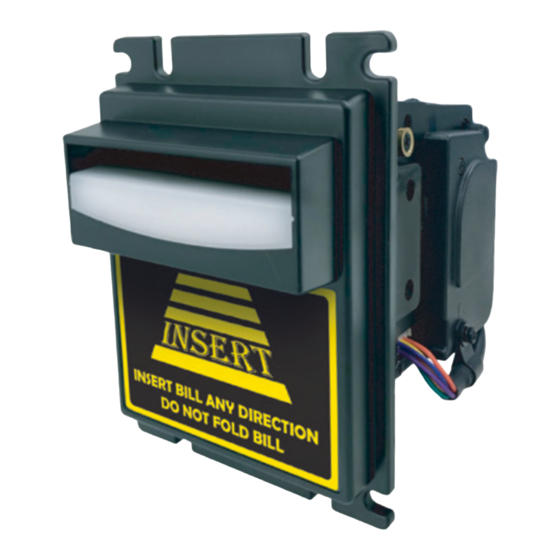
TP Series 1. Introduction 1-1. Overview TP series is a new generation of bill acceptor designed by TOPVME which features High-security with acceptance rate up to 96%. In addition,multiple bezel and bill box selections offer users the most convenient and complete services. -
Page 5: Specifications
Bill Acceptors 2. Specifications 2-1. General Acceptance Rate 96% or gr eater Interface Pulse/RS232、Pulse/ccTalk、Pulse/ID003 Installation Indoor Bill Inser tion Four way acceptable 2-2. Electrical Power Source 12V DC ±5% 12V DC Power Consumption Standby : 350mA / 4.2W Motor Lock : 2A / 24W Operation Temperature : 0°... -
Page 6: Dimension
TP Series 4. Dimension Unit : mm [ inch ] TP1/TP1-P5 Upper Bezel 122.78 4.834 93 3.661 93 3.661 122.78 4.834 98.80 3.890 98.80 3.890 84.30 3.319 84.30 3.319 5.41 0.213 5.41 0.213 81.30 3.201 81.30 3.201 51 2.008 51 2.008 169.15 6.659... - Page 7 Bill Acceptors Unit : mm [ inch ] TP1-P8 Upper Bezel 93 3.66 204.1 8.04 84.30 3.32 41.40 1.63 51 2.01 5.10 0.20 17.50 0.69 82.90 3.264 91.69 3.61...
- Page 8 TP Series Unit : mm [ inch ] TP1/TP1-P5-Middle Bezel 91.99 3.62 91.99 3.62 82.80 3.26 82.80 3.26 136.47 5.37 136.47 5.37 50.60 1.99 100.69 3.96 50.60 1.99 100.69 3.96 83.19 3.28 83.19 3.28 10.20 0.40 10.20 0.40 169.25 6.663 169.25 6.663...
- Page 9 Bill Acceptors Unit : mm [ inch ] TP1-P8-Middle Bezel 204.1 8.04 91.99 3.622 53.28 2.098 82.80 3.260 17.50 0.689 50.60 1.992 82.90 3.264 91.69 3.61...
- Page 10 TP Series Unit : mm [ inch ] TP2/TP2-P5 Upper Bezel 127.50 5.020 102.40 4.031 98.80 3.890 84 3.307 81.30 3.201 50.80 2.000 13.15 0.518 174.88 6.885 102.40 4.031 46.20 1.819 84 3.307 17.50 0.689 50.80 2.000 92.85 3.655...
- Page 11 Bill Acceptors Unit : mm [ inch ] TP2/TP2-P5 Middle Bezel 127.50 5.020 98.60 3.882 81.30 3.201 99.65 3.923 83.50 3.287 50.80 2.000 5.33 0.210 175.37 6.904 175.37 6.904 99.65 3.923 99.65 3.923 46.20 1.819 83.50 3.287 83.50 3.287 46.20 1.819 17.30 0.681 17.30 0.681 50.80 2.000...
- Page 12 TP Series Unit : mm [ inch ] TP3 Middle Bezel 105.65 4.159 105.65 4.159 83.12 3.272 83.12 3.272 83.50 3.287 83.50 3.287 80.15 3.156 80.15 3.156 50.30 1.980 5.33 0.210 50.30 1.980 5.33 0.210 TP1-K Upper Bezel 93 3.66 5.20 0.20...
-
Page 13: Installation
Bill Acceptors 5. Installation 5-1. Harness Application Interface Voltage Usage Harness Page Power & Data Communication WEL-R7U02 PULSE Extension Cable CU-R961-1 Power & Data Communication WEL-R7U02 12V DC Extension Cable CU-R961-1 RS232 Data WEL-R7U06 Communication NOTE : Software download Please refer to the G-BOX instruction manual for the download manual. - Page 14 TP Series WEL-R7U02 PIN NO COLOR PIN DEFINE PIN NO COLOR PIN DEFINE +12V DC PIN1 YELLOW INHIBIT+ PIN1 PIN2 GREEN INHIBIT- PIN2 ORANGE +12V DC PIN5 PIN3 YELLOW INHIBIT+ PIN7 BLUE METER+ PIN4 GREEN INHIBIT- PIN8 PURPLE METER- PIN5...
- Page 15 Bill Acceptors CU-R961-1 PIN NO COLOR PIN DEFINE PIN1 YELLOW INHIBIT+ PIN2 GREEN INHIBIT- PIN5 +12V DC PIN7 BLUE METER+ METER- PIN8 PURPLE PIN9 ORANGE...
- Page 16 TP Series WEL-R7U06 PIN NO COLOR PIN DEFINE PIN1 BLUE PIN NO PIN DEFINE PIN2 PIN6 WHITE PIN3 PIN7 BLACK PIN5 PIN8 PURPLE...
-
Page 17: I/O Circuit
Bill Acceptors 5-2. I/O Circuit PULSE INTERFACE Credit_Relay_NO Credit_Relay_COM Bill Acceptor Customer Side Inhibit (+) Inhibit (-) TR ON TR OFF Bill Acceptor Customer Side BA Status DIP SW Setting Control Signal Inhibit Inhibit Active High High High Inhibit Enable Active High... - Page 18 TP Series Standard RS232 Protocol...
-
Page 19: Dip Switch Setting
Bill Acceptors 5-3. DIP Switch Setting There are DIP switches located at the sides of the TP series. Varying on different currencies and credit output formats used; the DIP switch settingd could vary to fit user's needs. The DIP switch located at the bottom of the TP series is intended for interface settings.Please refer to the "TP Series... -
Page 20: Maintenance
TP Series 6. Maintenance Foreign objects on the LED or sensor may cause bill jamming and decrease acceptance rate.To make sure the bill acceptor always works smoothly,please clean the internal parts regularly. To clean the internal parts : 1. Turn Bill Acceptor off. - Page 21 Taiwan Top Vending Machine Electronics Co., Ltd. NO.11, Anzhong St., Luzhu Dist., Taoyuan City338, Taiwan, (R.O.C.) Phone : +886-3-3115969.Fax : +886-3-3115970 E-mail : sales@topvme.com.tw Website : www.topvme.com...
- Page 22 Top Vending Machine Electronics Co., Ltd. w w w .topv me .co m...
Need help?
Do you have a question about the TP Series and is the answer not in the manual?
Questions and answers
Hello. Can I manually calibrate and update my bill acceptor (tp70). Can you tell me how. Thank you so much for your help. Looking forward
What are the settings of tp70p3b dip switch