Table of Contents
Advertisement
Quick Links
Advertisement
Table of Contents

Summary of Contents for Logicbus 3540 M
- Page 1 7/14/98 User's Manual 3540 M Step Motor Driver...
- Page 2 Technical Specifications Introduction Amplifiers Dual, bipolar MOSFET H-bridge, pulse width modulated three Thank you for selecting an Applied Motion Products motor control. We hope our state switching at 20kHz. 12-42 VDC input. 0.4 - 3.5 dedication to performance, quality and economy will make your motion control amps/phase output current, switch selectable in 0.1 A project successful.
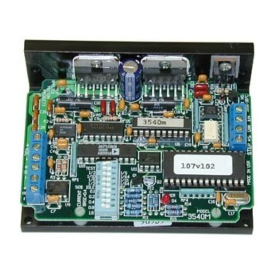
- Page 3 Mechanical Outline Getting Started To use your Applied Motion Products motor control, you will need the following: 4x Ø.125 • a 12-42 volt DC power supply for the motor. Please read the section entitled 1.50" 0.125" 2.50" Choosing a Power Supply for help in choosing the right power supply. •...
- Page 4 Connecting the Power Supply Mounting the Drive If you need information about choosing a power supply, please read Choosing a Power Supply located on page 12 of this manual. The PS430 from Applied Motion You can mount your drive on the wide or the narrow side of the chassis. If you Products is a good supply for this drive.
- Page 5 However, you will generally need a lot less than that, depending on the motor type, Orange Orange voltage, speed and load conditions. That's because the 3540 M uses switching amplifiers, converting a high voltage and low current into lower voltage and higher Blk/Wht Org/Wht current.
- Page 6 The 3540 M includes a self test feature. This is used for trouble shooting. If you are unsure about the motor or signal connections to the drive, or if the 3540 M isn't ENABLE allows the user to turn off the current to the motor by setting this signal to responding to your step pulses, you can turn on the self test.
- Page 7 +V (12-42 volts DC) INPUT SIGNALS Setting the step resolution is easy. Look at the dip switch on the 3540 M. Next to STEP switches 2 and 3, there are labels on the printed circuit board. Each switch has two 3540 M markings on each end.
- Page 8 The rated current is usually printed on the motor label. The 3540 M drive current is easy to set. If you wish, you can learn a simple formula for setting current and never need the manual again. Or you can skip to the table on...
Need help?
Do you have a question about the 3540 M and is the answer not in the manual?
Questions and answers