Advertisement
Quick Links
Kit Number KU-24640
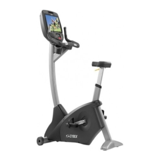
This instruction sheet describes how to install the Netpulse upgrade kit for Cybex bike model 770C or
770R.
Tools Required
Phillips screwdriver
•
1/2" Wrench
•
7/16" Wrench
•
5/16" Allen wrench
•
Read and understand all instructions thoroughly before installing this kit.
Verify the kit contents shown. Netpulse monitor not included.
1
2
3
4
5
6
12
13
15
16
17
Netpulse Upgrade Kit, 770C/770R
7
14
Page 1 of 12
Installation Instructions
Description
1
Back cover, PL-24438
2
5/16" Locknut, HN-42063
3
Washer, HW-18123
11
4
Bolt, HS-18157
5
1" Bolt (6), HS-00489
6
1/4" Locknut (6), HN-12079
7
1/2" Screw (2), HS-21672
10
8
Hood, AF-24436
9
Decal, DE-24616
9
10 Vesa mount, HX-24440
11 Monitor bracket, AF-24437
8
12 Coupler, RJ45, CN-22747
13 Coupler, Right angle,
CN-24518
14 Coupler, Coax, CN-24519
15 CSAFE cable, AW-24522
16 CAT6 cable, AW-24521
17 Power and COAX cable,
AW-24523
www.cybexintl.com
Advertisement

Summary of Contents for CYBEX Netpulse 770C
- Page 1 Netpulse Upgrade Kit, 770C/770R Installation Instructions Kit Number KU-24640 This instruction sheet describes how to install the Netpulse upgrade kit for Cybex bike model 770C or 770R. Tools Required Phillips screwdriver • 1/2” Wrench • 7/16” Wrench • 5/16” Allen wrench •...
- Page 2 Disconnect optional external power source Unplug power cord from the power outlet. WARNING: Shock and electrocution hazard Unplug unit and let sit 10 minutes before cleaning or performing maintenance • Electrical charge can remain in unit after unplugging • Keep water and liquids away from electrical parts •...
- Page 3 Remove console assembly 1. Remove the six screws securing the console assembly to the console support using a Phillips screwdriver. Description Console assembly MCC board Console support Screws (6) 2. Unplug cables from the MCC board by un-latching connectors with the following procedure: A.
- Page 4 MCC board cables Description Wireless audio (optional) CSAFE (optional) Display LED display board Headphone jack iPod (optional) Heart rate Handset membrane 10 iPod board assembly (optional) 3. Unplug CardioTouch cable. The CardioTouch cable is held in place by a notch in the access cover.
- Page 5 Remove console support screws Remove and discard the six screws securing the console support to the weldment using a Phillips screwdriver. Description Console support Weldment Screw (6) Assemble monitor bracket 1. Install the two 1/2” screws securing the hood to the monitor bracket using a Phillips screwdriver.
- Page 6 2. Install the bolt, washer, and 5/16” locknut securing the Vesa mount to the monitor bracket using a 5/16” Allen wrench and a 1/2” wrench. Description Bolt Washer 5/16” Locknut Vesa mount Monitor bracket Install monitor bracket 1. Install the six bolts securing the console support to the weldment using a 7/16” wrench. Description 1/4”...
- Page 7 Remove front covers 770C Remove the two screws securing the front right cover using a Phillips screwdriver. Description Front right cover Screws (2) 770R Remove the three screws securing the front left cover using a Phillips screwdriver. Description Plastic connectors Front left cover Screws (2) In addition to the mounting screws, there are five plastic connectors that secure the front covers...
- Page 8 Route cables 1. Route the power and COAX cable, and the CAT6 cables through the top of the monitor bracket and down into the weldment. The CAT6 cable will plug into the console. Description Monitor bracket Weldment Power and COAX CAT6 CSAFE 770C...
- Page 9 770R Route the power and coax cable, and CAT6 cable into the top of the upright tube until it exits through the lower hole in the upright tube. Description Cables Upright tube Lower hole Install front covers 770C Install the two screws securing the front right cover using a Phillips screwdriver. Description Front right cover Screws (2)
- Page 10 770R Install the three screws securing the front right cover using a Phillips screwdriver. Description Plastic connectors Front left cover Screws (2) In addition to the mounting screws, there are five plastic connectors that secure the front covers together. Ensure that all five plastic connectors are inserted properly in each front cover. Install console assembly 1.
- Page 11 2. Install the six screws securing the console assembly to the console support using a Phillips screwdriver. Description Console Assembly Console Support Screw (6) Install back cover Install the four screws securing the back cover to the console assembly using a Phillips screwdriver. Description Console assembly Back cover...
- Page 12 Cybex® and the Cybex logo are registered trademarks of Cybex International, Inc. 10 Trotter Drive Medway, MA 02053 508-533-4300 • FAX 508-533-5183 • www.cybexintl.com Copyright © 2013, Cybex International, Inc. All rights reserved • LT-24878-4 A • November 2013 Page 12 of 12 www.cybexintl.com...
Need help?
Do you have a question about the Netpulse 770C and is the answer not in the manual?
Questions and answers