Advertisement
Quick Links
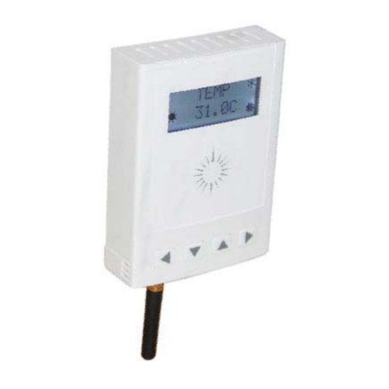
Descriptions
This full-featured CPU based thermostat is designed for small cooling and heating air handling sys-
tems in residential and commercial facilities. The unit provides features which eclipse standard me-
chanical thermostats at a price that fi ts conventional HVAC projects.
Highlights:
-Tight control of 0.5°C provides comfortable indoor environment.
-High impact plastic enclosure provides durability in commercial environments.
-Customizable sequence of operation table (FCU with modulating or on/off valve,single or 3-speed fan,
pressure independent VAV, stage sequencer)
-Available in Clock, Clock & Humidity, CO2 ,OCC and Zigbee options
Tstat6
Tstat6-CH
TSTAT6-CO2
TSTAT6-ZIGB
TSTAT6-OCC
Tstat6
Sales Price
39
44
90
55
41
Discount Price
37
42
75
53
39
- 1 -
Tstat Series
OEM>50k/yr
36
41
60
51
38
Advertisement

Summary of Contents for Frigor Tstat Series
- Page 1 Tstat Series Tstat6 Descriptions This full-featured CPU based thermostat is designed for small cooling and heating air handling sys- tems in residential and commercial facilities. The unit provides features which eclipse standard me- chanical thermostats at a price that fi ts conventional HVAC projects.
- Page 2 Tstat Series Tstat6 Technical Data 5 relays x 2amps @24V, 7 analog inputs, TSTAT6 2 analog outputs (10V @100ma) Operating temperature -30-70°C(-22~158°F) Supply voltage 12~24VAC/DC ±20%, 50-60Hz Power consumption 100mA at 12VDC Relay contacts rating 2A @ 24VDC, 0.5A @ 125VAC UL File No.: E43149...
- Page 3 Tstat Series Tstat6-C or Tstat-CH Technical Data genuine Tstat6 with Clock or Humidity options, they added some new features. 1. Temperature range: indoor & outdoor -30 °C ~ + 70 °C ( -22 ~ +158 °F ) Humidity range : indoor 10% ~ 90%RH Power - supply : 100mA at 12VDC 2.
-
Page 4: Supply Voltage
Tstat Series Light Sensor Module Technical Data The light Sensor module is a standard item now. It just provides an illuminance value. It is de- signed with TPS851. This device enables low power consumption to be achieved. • Little fl uctuation in light current and high level of sensitivity : IL = 37 μA to 74 μA @EV = 100 lx using fl... -
Page 5: Supply Current
Tstat Series Electrical and Optical Characteristics (Ta 25°C) Characteristics Symbol Test Condition Min Typ. Max Unit Supply current VCC =3 V, EV=1000 lx RL =1 k Ω (Note — — μ A Light current (1) IL (1) VCC =3 V, EV=1000 lx (Note 2) , —... - Page 6 Tstat Series - 6 -...
- Page 7 Tstat Series - 7 -...
- Page 8 Tstat Series Switching Time Measurement Circuit and Waveforms - 8 -...
- Page 9 Tstat Series Tstat6 Highlights - 9 -...
- Page 10 Tstat Series Tstat6 Jumper Settings Tstat6 Wiring Diagram - 10 -...
- Page 11 Tstat Series Tstat6-CO2 Highlights Tstat6-CO2 Jumper Settings - 11 -...
- Page 12 Tstat Series Tstat6-CO2 Wiring Diagram - 12 -...
- Page 13 Tstat Series Tstat6-Zigbee Highlights - 13 -...
- Page 14 Tstat Series Tstat6-Zigbee Jumper Settings Tstat6-Zigbee Wiring Diagram - 14 -...
- Page 15 Tstat Series Tstat6-OCC Highlights - 15 -...
- Page 16 Tstat Series Tstat6-OCC Jumper Settings Tstat6-OCC Wiring Diagram - 16 -...
- Page 17 Tstat Series Advanced Menu Item Details The Tstat6 series thermostats have several advanced menu items which can be adjusted in the fi eld to suit the application and tune the operation of the thermostat. Generally speaking, all the parameters are set up at the factory on an order-by-order basis and will give satisfactory results out of the box.
- Page 18 Tstat Series Code Description (Range, Default) Modbus Device Address (1-254, 254) This is the modbus address of the tstat. It is the address to which the stat will respond when receiving serial communication. Calibration of the Selected Temperature Sensor (0-1000, 500) To calibrate the temperature shown on the tstat display you will need a handheld mercury thermometer or digital thermometer.
- Page 19 Tstat Series Code Description (Range, Default) Proportional Term (10-255, 20) The proportional term is the ‘P’ term of the familiar PID control strategy and determines how fast a valve will react to a deviation from setpoint at a particular instant in time. The default value of 2.0° (C or F) is fi ne for most applications, where a 2.0° deviation is required to make the valve respond 100%.
- Page 20 Tstat Series Code Description (Range, Default) Heating & Cooling Deadbands (1-200, 10) If there is one setpoint, the heating setpoint follows the cooling setpoint and is calculated by: Heating Setpoint = Setpoint - Heating Deadband. Cooling Setpoint = Setpoint + Cooling Deadband If there are two setpoints, heating and cooling are separately adjusted.
- Page 21 Tstat Series Code Description (Range, Default) Output settings (0-4, 0) Sets the full-scale voltage of the analog outputs. Ou1 sets analog out 1 (Cooling). Ou2 sets analog out 2 (Heating). This setting is used to match the analog outputs to various types of actuators, transducers or other controllers.
- Page 22 Tstat Series TSTAT6-CO2 calibration 1. Connect TSTAT6-CO2 to PC by RS485. 2. Open T3000 and it show the following view. 3. Click the button to scan, the following view will appear and close it as the picture shows. - 22 -...
- Page 23 Tstat Series 4. Click the TSTAT6 log and it will show all the information of TSTAT6. 5. Click button input , it will show all the information of input, same as output. When you press input1, you can change the name according to your demand.
- Page 24 Tstat Series 6. There is one list of Auto/Manual, when press manual, the value can be set by the customer. When you press auto, it will change automatically according to the temperature, and when you press cali- bration, you can adjust the value.
- Page 25 Tstat Series 6. When press the setting button, it will show the parameter view. When press PIDs Table, it will open 3 PID view. - 25 -...
- Page 26 Tstat Series - 26 -...
- Page 27 Tstat Series Tstat6: Getting Started This example will show you how to properly set up a new Tstat6 and attach a couple external devices to the unit. In this example we will use a DTS-FL-4-6-7 temperature sensor and a PSN 30-300A air differential pressure switch, to be read by the Tstat6.
- Page 28 Tstat Series Start the T3000 program. If you do not want to clear the building view to create an easier working space than skip to step 6. Otherwise go to the menu and select “Database >> All Nodes” and click the “Del All” button to clear the ‘Default Buildings’...
- Page 29 Tstat Series Now click the “Discover” button, circled green in the picture above. T3000 will actively search your computer’s ports and fi nd the Tstat6 that is connected. Once it has fi nished it will show a pop up window, shown below, with the Tstat6’s information shown.
- Page 30 Tstat Series We now must pick the appropriate ranges, according to our devices, so that the values being displayed will be meaning- ful for that partiuclar input. To do this, click on the box under the range column, representing which input you want to adjust.
- Page 31 Tstat Series - 31 -...
- Page 32 Tstat Series Register of Tstat6 Address Register Name Register and Description MODBUS_SERIALNUMBER_LOWORD Serial Number - 4 byte value. Read-only RESERVED Serial Number - 4 byte value. Read-only MODBUS_SERIALNUMBER_HIWORD Serial Number - 4 byte value. Read-only RESERVED Serial Number - 4 byte value. Read-only MODBUS_VERSION_NUMBER_LO Software Version –...
- Page 33 Tstat Series Address Register Name Register and Description RESERVED Security key RESERVED Security key RESERVED Security key RESERVED Security key RESERVED Security key RESERVED Security key RESERVED Security key RESERVED Security key RESERVED Security key RESERVED Security key RESERVED Security key...
- Page 34 Tstat Series Address Register Name Register and Description RESERVED Blank, for future use RESERVED Blank, for future use RESERVED Blank, for future use RESERVED Blank, for future use RESERVED Blank, for future use RESERVED Blank, for future use RESERVED Blank, for future use...
- Page 35 Tstat Series Address Register Name Register and Description "Info Byte, this register contains info about the state of the tstat. Bit 0 is read/ write and shows the occupancy mode. Bit 0 = 0 means unoccupied. Bit 0 = 1 means occupied. Bit 1 is read only and shows the reset state. Bit 1 = 0 means hardware restart.
- Page 36 Tstat Series Address Register Name Register and Description ANALOG INPUT3 RANGE. 0 = raw data, 1 = thermistor, 2 = %, 3 = ON/OFF, MODBUS_ANALOG3_RANGE 4 = N/A, 5 = OFF/ON ANALOG INPUT4 RANGE. 0 = raw data, 1 = thermistor, 2 = %, 3 = ON/OFF,...
- Page 37 Tstat Series Address Register Name Register and Description MODBUS_CALIBRATION_ANALOG2 Calibration for analog input2 MODBUS_CALIBRATION_ANALOG3 Calibration for analog input3 MODBUS_CALIBRATION_ANALOG4 Calibration for analog input4 MODBUS_CALIBRATION_ANALOG5 Calibration for analog input5 MODBUS_CALIBRATION_ANALOG6 Calibration for analog input6 MODBUS_CALIBRATION_ANALOG7 Calibration for analog input7 MODBUS_CALIBRATION_ANALOG8 Calibration for analog input8...
- Page 38 Tstat Series Address Register Name Register and Description MODBUS_TABLE2_HALFONE Lookup Table 2 - 0.5V value Sensor value that corresponds to 0.5V MODBUS_TABLE2_ONE Lookup Table 2 - 1.0V value Sensor value that corresponds to 1.0V MODBUS_TABLE2_HALFTWO Lookup Table 2 - 1.5V value Sensor value that corresponds to 1.5V MODBUS_TABLE2_TWO Lookup Table 2 - 2.0V value Sensor value that corresponds to 2.0V...
- Page 39 Tstat Series Address Register Name Register and Description MODBUS_OUTPUT6_DELAY_OFF_TO_ (future)Output6 delay_OFF_TO_ON – delay time for output4 going from OFF to ON (sec) MODBUS_OUTPUT7_DELAY_OFF_TO_ (future)Output7 delay_OFF_TO_ON – delay time for output5 going from OFF to ON (sec) MODBUS_DELAY1_OFF_TO_ON_TIME_ Output 1 current time left from OFF to ON...
- Page 40 Tstat Series Address Register Name Register and Description "MODBUS_CHANGOVER_DELAY – delay time (in minutes) for switching from MODBUS_CHANGOVER_DELAY cooling into heating or vice versa." Valve travel time. The time of the valve travel from one end to another end. The MODBUS_VALVE_TRAVEL_TIME units is second.
- Page 41 Tstat Series Address Register Name Register and Description Auto Manual mode for outputs, bit 0 = relay1, bit1 = relay2… bit 5 = (out6) analog- MODBUS_OUTPUT_MANU_EN- out1, bit6 = (out7) analogout2. In manual mode you can write to the output registers ABLE for debugging or from an external master to override the local PID logic.
- Page 42 Tstat Series Address Register Name Register and Description MODBUS_UNIVERSAL_OUTPUT_ PID2 Output table- Cooling2 COOL2 MODBUS_UNIVERSAL_OUTPUT_ PID2 Output table- Cooling3 COOL3 MODBUS_UNIVERSAL_OUTPUT_ PID2 Output - Heating1 HEAT1 MODBUS_UNIVERSAL_OUTPUT_ PID2 Output - Heating HEAT2 MODBUS_UNIVERSAL_OUTPUT_ PID2 Output - Heating3 HEAT3 MODBUS_FAN0_OPER_TABLE_ FAN0_OPERATION_TABLE_COAST...
- Page 43 Tstat Series Address Register Name Register and Description MODBUS_FAN2_OPER_TABLE_HEAT2 FAN2_OPERATION_TABLE_HEAT2 MODBUS_FAN2_OPER_TABLE_HEAT3 FAN2_OPERATION_TABLE_HEAT3 MODBUS_FAN3_OPER_TABLE_COAST FAN3_OPERATION_TABLE_COAST MODBUS_FAN3_OPER_TABLE_COOL1 FAN3_OPERATION_TABLE_COOL1 MODBUS_FAN3_OPER_TABLE_COOL2 FAN3_OPERATION_TABLE_COOL2 MODBUS_FAN3_OPER_TABLE_COOL3 FAN3_OPERATION_TABLE_COOL3 MODBUS_FAN3_OPER_TABLE_HEAT1 FAN3_OPERATION_TABLE_HEAT1 MODBUS_FAN3_OPER_TABLE_HEAT2 FAN3_OPERATION_TABLE_HEAT2 MODBUS_FAN3_OPER_TABLE_HEAT3 FAN3_OPERATION_TABLE_HEAT3 MODBUS_FANAUT_OPER_TABLE_COAST FANAUT_OPERATION_TABLE_COAST MODBUS_FANAUT_OPER_TABLE_COOL1 FANAUT_OPERATION_TABLE_COOL1 MODBUS_FANAUT_OPER_TABLE_COOL2 FANAUT_OPERATION_TABLE_COOL2 MODBUS_FANAUT_OPER_TABLE_COOL3 FANAUT_OPERATION_TABLE_COOL3 MODBUS_FANAUT_OPER_TABLE_HEAT1 FANAUT_OPERATION_TABLE_HEAT1 MODBUS_FANAUT_OPER_TABLE_HEAT2 FANAUT_OPERATION_TABLE_HEAT2 MODBUS_FANAUT_OPER_TABLE_HEAT3 FANAUT_OPERATION_TABLE_HEAT3...
- Page 44 Tstat Series Address Register Name Register and Description (Day)Occupied cooling setpoint dead band , offset from setpoint for MODBUS_DAY_COOLING_DEADBAND cooling to begin. Units are 0.1 deg. (Day)Occupied heating setpoint dead band , offset from setpoint for MODBUS_DAY_HEATING_DEADBAND heating to begin. Units are 0.1 deg.
- Page 45 Tstat Series Address Register Name Register and Description MODBUS_UNOCCUPIED_COOLING Reserved,unoccupied cooling MODBUS_RH_SETPOINT Reserved,humidity setpoint MODBUS_CURRENT1_SETPOINT Reserved,cuurent1 setpoint Sensor to be used for the PID calculations, 1= external sensor analog input 1 , MODBUS_TEMP_SELECT 2 = internal thermistor, 3 = average the internal thermistor and analog input1...
- Page 46 Tstat Series Address Register Name Register and Description "SPECIAL_MENU_LOCK, Special menu lockout via keypad, serial port only, 0=Full Menu, 1=Menu Disabled, 2=Typical small menu system, 3 = The user can adjust the setpoint in menu mode, 4 = Partial menu enabled When the LOC parameter isset to ‘1’...
- Page 47 Tstat Series Address Register Name Register and Description MODBUS_MONTH Clock,month MODBUS_WEEK Clock,week MODBUS_DAY Clock,day MODBUS_HOUR Clock, hours MODBUS_MINUTE Clock,minutes MODBUS_SECOND Clock,seconds MODBUS_DIAGNOSTIC_ALARM Alarm,not used now MODBUS_DAY1_EVENT1_HI Work day,wake time hour MODBUS_DAY1_EVENT1_LO Work day,wake time minutes MODBUS_DAY1_EVENT2_HI Work day,away time,hour MODBUS_DAY1_EVENT2_LO...
- Page 48 Tstat Series Address Register Name Register and Description MODBUS_AI2_CHAR3 Input 2 user name. line 1:characters 5 & 6 MODBUS_AI2_CHAR4 Input 2 user name. line 1:characters 7 & 8 MODBUS_AI3_CHAR1 Input 3 user name. line 1:characters 1 & 2 MODBUS_AI3_CHAR2 Input 3 user name. line 1:characters 3 & 4 MODBUS_AI3_CHAR3 Input 3 user name.
- Page 49 Tstat Series PID2 VALVE OFF TABLE HEATING2 PID2 VALVE OFF TABLE HEATING3 Spare Value of light sensor PIR sensor select 1=PIR sensor enable 0=PIR sensor disable PIR sensor real value PIR sensor range 0:unocupied 1: occupied PID2 VALVE TABLE COASTING...
- Page 50 Tstat Series Address Register Name Register and Description MODBUS_OUTPUT5_CHAR1 Output 5 user name. line 1:characters 1 & 2 MODBUS_OUTPUT5_CHAR2 Output 5 user name. line 1:characters 3 & 4 MODBUS_OUTPUT5_CHAR3 Output 5 user name. line 1:characters 5 & 6 MODBUS_OUTPUT5_CHAR4 Output 5 user name. line 1:characters 7 & 8 MODBUS_OUTPUT6_CHAR1 Output 6 user name.
- Page 51 Tstat Series Address Register Name Register and Description MODBUS_AVERAGE_CHAR4 Average character 4 MODBUS_LCD_SCREEN1 LCD screen1,select which information will display on LCD,range0 to 12 MODBUS_LCD_SCREEN2 LCD screen2,select which information will display on LCD,range0 to 12 MODBUS_DEMAND_RESPONSE Demand response fl ag 0: disable 1:yes 2:no (reserved)All registers except fan speed and manual input are not writable.0 =...
- Page 52 Tstat Series Address Register Name Register and Description MODBUS_DISP_ITEM_AI8 Decide which item will be shown in the display sequency.see up note MODBUS_DISP_ITEM_MODE Decide which item will be shown in the display sequency.see up note MODBUS_DISP_ITEM_USER_INFO Decide which item will be shown in the display sequency.see up note MODBUS_DISP_ITEM_CLOCK_ Decide which item will be shown in the display sequency.see up note...
- Page 53 Tstat Series Address Register Name Register and Description MODBUS_PWM_OUT4 Spare MODBUS_PWM_OUT5 Spare MODBUS_SUN_ICON_CONTROL Spare MODBUS_MOON_ICON_CONTROL Spare MODBUS_EXT_SENSOR_TEMP_ Calibration data of thermistor which on external humidity sensor MODBUS_BUTTON_LEFT1 Keypad defi ne : default value:128,64,8,4. MODBUS_BUTTON_LEFT2 Keypad defi ne : default value:128,64,8,4.
- Page 54 Tstat Series Address Register Name Register and Description MODBUS_UNIVERSAL_OFF_ PID2 VALVE OFF TABLE HEATING2 VALVE_HEAT2 MODBUS_UNIVERSAL_OFF_ PID2 VALVE OFF TABLE HEATING3 VALVE_HEAT3 RESERVED Spare MODBUS_VALUE_SENSOR Value of light sensor MODBUS_PIR_SELECT_ENABLE PIR sensor select 1=PIR sensor enable 0=PIR sensor disable MODBUS_PIR_REAL_VALUE...
- Page 55 Tstat Series Address Register Name Register and Description MODBUS_PID3_VALVE_OPER_TA- (VAV function) PID3_VALVE_OPER_TABLE_COOL3 BLE_COOL3 MODBUS_PID3_VALVE_OPER_TA- (VAV function) PID3_VALVE_OPER_TABLE_HEAT1 BLE_HEAT1 MODBUS_PID3_VALVE_OPER_TA- (VAV function) PID3_VALVE_OPER_TABLE_HEAT2 BLE_HEAT2 MODBUS_PID3_VALVE_OPER_TA- (VAV function) PID3_VALVE_OPER_TABLE_HEAT3 BLE_HEAT3 MODBUS_PID3_COOLING_DB (VAV function) PID3 cooling deadband MODBUS_PID3_HEATING_DB (VAV function) PID3 heating deadband...
- Page 56 Tstat Series Address Register Name Register and Description MODBUS_PID3_OFF_OUTPUT_ (VAV function) PID3_DIGITAL_OFF_OUTPUT_HEAT2 HEAT2 MODBUS_PID3_OFF_OUTPUT_ (VAV function) PID3_DIGITAL_OFF_OUTPUT_HEAT3 HEAT3 MODBUS_WIRELESS_PIR_RE- MODBUS_WIRELESS_PIR_RESPONSE1 SPONSE1 MODBUS_WIRELESS_PIR_RE- MODBUS_WIRELESS_PIR_RESPONSE2 SPONSE2 MODBUS_WIRELESS_PIR_RE- MODBUS_WIRELESS_PIR_RESPONSE3 SPONSE3 MODBUS_WIRELESS_PIR_RE- MODBUS_WIRELESS_PIR_RESPONSE4 SPONSE4 MODBUS_WIRELESS_PIR_RE- MODBUS_WIRELESS_PIR_RESPONSE5 SPONSE5 - 56 -...
Need help?
Do you have a question about the Tstat Series and is the answer not in the manual?
Questions and answers