Table of Contents
Advertisement
Quick Links
Energy Technology srl
Operating office :
Via della Solidarieta 2/1
40056 Valsamoggia – Loc. Crespellano (BO) – Italy
Ph : + 39 051 6656 611 Fax : +39 051 6656 677
–
ocem@ocem.com
www.ocem.com
VAT Nr : IT 031 4821 1208
a division of Energy Technology srl
DIAM 3100
DIAM 4100
DIAM 3200
DIAM 4200
Cut out
Installation & maintenance
Compliance with standards:
ICAO Aerodrom design manual, part 5
IEC 61822 et 61821
FAA (AC 150/5345-10F Spec.L828/L829)
AENA: PPT/002-05/13
Advertisement
Table of Contents

Summary of Contents for AUGIER Energy DIAM 3100
- Page 1 Ph : + 39 051 6656 611 Fax : +39 051 6656 677 – ocem@ocem.com www.ocem.com VAT Nr : IT 031 4821 1208 a division of Energy Technology srl Installation & maintenance DIAM 3100 DIAM 4100 DIAM 3200 DIAM 4200 Cut out Compliance with standards: ICAO Aerodrom design manual, part 5 IEC 61822 et 61821 FAA (AC 150/5345-10F Spec.L828/L829)
- Page 2 6021752 DIAMXXXX CUT OUT rev 1-0.doc...
-
Page 3: Record Of Change
RECORD OF CHANGES Rev. Pages Description From S/N App. Date First issue 31/01/19 6021752 DIAMXXXX CUT OUT rev 1-0.doc... -
Page 4: Warranties
WARRANTIES Guarantee AUGIER’s goods has been manufactured and will perform in accordance with applicable specifications, and any defect in design, materials or workmanship which may occur during proper and normal use during a period of 1 year from date of installation or 2 years from date of shipment will be corrected by repair or replacement by the manufacturers f.o.b factory. -
Page 5: Safety
SAFETY Safety precautions This equipment is normally used or connected to circuits that may employ dangerous and lethal voltages. Extreme caution should be exercised by operating or maintenance people when working on or with this equipment. See IEC 61820 & 61821 standard (CCR type IEC), or FAA AC150/5340-26 advisory circular (CCR type FAA), concerning safety rules and precautions. -
Page 6: Table Of Contents
TABLE OF CONTENTS RECORD OF CHANGE……………………………………………………………………………………… WARRANTIES ……………………………………………………………………………………………… SAFETY ………………………………………………………………………………………………….….. TABLE OF CONTENTS……………………………………………………………………………………… _______________________________________________________________________ DESCRIPTION ___________________________________________________________________ I-10 OVERVIEW ____________________________________________________________________ I-10 MODELS ____________________________________________________________________________ ___________________________________________________________________ II-12 II.1 SIMALT 1 _____________________________________________________________________ II-12 II.1.1 DESCRIPTION _____________________________________________________________ II-12 II.1.2 SERVICE POSITION : ________________________________________________________ II-12 II.1.2.1 SAFETY POSITION: _____________________________________________________ II-12 II.1.2.2 LOAD MEASUREMENT POSITION: _________________________________________ II-13... - Page 7 II.5.7 CIMALT MAINTENANCE II-21 II.6 CO-OCEM ____________________________________________________________________ II-24 II.6.1 DESCRIPTION _____________________________________________________________ II-24 II.6.2 OVERVIEW _______________________________________________________________ II-24 II.6.3 CCR SETTING _____________________________________________________________ II-25 II.6.4 MA SWITCH _______________________________________________________________ II-25 II.6.5 MB SWITCH _______________________________________________________________ II-25 II.6.6 SERVICE POSITION: ________________________________________________________ II-26 II.6.7 SAFETY POSITION: ________________________________________________________ II-26 II.6.8 LOAD MEASUREMENT POSITION: ____________________________________________ II-26 SPARE PARTS LIST _____________________________________________ III-27...
- Page 8 ABBREVIATIONS Abbreviation Definition Ampere Alternating Current Brightness Constant Current Regulator Direct Current Earth Fault Detector High Voltage Injection Transformer Lamp Fault Detector Low Voltage Out of order Volt Volt-Ampere 6021752 DIAMXXXX CUT OUT rev 1-0.doc...
- Page 9 6021752 DIAMXXXX CUT OUT rev 1-0.doc...
-
Page 10: Idescription
DESCRIPTION I.1 OVERVIEW The CCR can be fitted with CUT OUT switch. *This cut out is an additionnal part to help maintenance. The main function is to connect easily the loop to the earth. A second function is to measure the impedance loop. - Page 11 The cut out has 3 positions: SERVICE MAINTENANCE or SAFETY MEASUREMENT See Note 1 Note 1: No measurement position for SEB cut cout. Standards: ICAO: Airport design manual, part 5 STNA: CCTP 91068 rev.93 CENELEC: prENV 50231 ...
-
Page 12: Models
MODELS II.1 SIMALT 1 II.1.1 DESCRIPTION AUGIER’s experience regarding CCRs has been used to simplify the HV compartment and maintenance operations to the maximum. With that option, the CCR is equipped with an cut-out and earthing plate, using two jumpers which allows to carry out all maintenance and measurement operations, without unscrewing any load terminal or earth connection, and without requiring any special tools. -
Page 13: Ii.1.2.2 Load Measurement Position
II.1.2.2 LOAD MEASUREMENT POSITION: Removing the lower jumper, CCR will be still short-circuited and earthed, but loop’s terminals will be let free, in order to allow to proceed at all insulation and continuity measurements, which can be carried out as well as any other testing or research operations concerning the load. -
Page 14: Ii.2 Simalt 2
II.2 SIMALT 2 AUGIER’s experience regarding CCRs has been used to simplify the HV compartment and maintenance operations to the maximum. With that option, the CCR is equipped with an cut-out and earthing plate, using two jumpers which allows to carry out all maintenance and measurement operations, without unscrewing any load terminal or earth connection, and without requiring any special tools. -
Page 15: Ii.2.1 Load Measurement Position
II.2.1 LOAD MEASUREMENT POSITION: Load measure By removing the two jumpers of L1, L2 , it is possible to measure the load. WARNING : The CCR can start in short circuit. and voltage can appear on the CCR output (1) and (2). 6021752 DIAMXXXX CUT OUT rev 1-0.doc II-15... -
Page 16: Ii.3 Simalt 3
II.3 SIMALT 3 AUGIER’s experience regarding CCRs has been used to simplify the HV compartment and maintenance operations to the maximum. With that option, the CCR is equipped with an cut-out and earthing plate, using two jumpers which allows to carry out all maintenance and measurement operations, without unscrewing any load terminal or earth connection, and without requiring any special tools. -
Page 17: Ii.3.1.2 Load Measurement Position
II.3.1.2 LOAD MEASUREMENT POSITION: Removing the L1 L2 jumper, CCR will be still short-circuited and earthed, but loop’s terminals will be let free, in order to allow to proceed at all insulation and continuity measurements, which can be carried out as well as any other testing or research operations concerning the load. -
Page 18: Ii.4 Seb
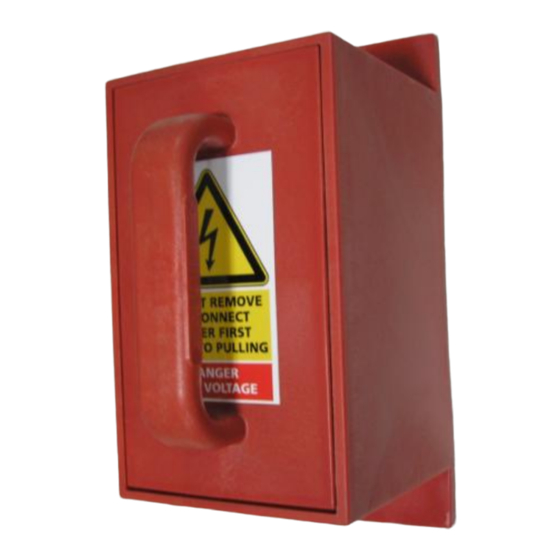
II.4 SEB II.4.1 DESCRIPTION The lighting circuit cut-out plug is a safety device that will realise the separation and short circuit of the constant current regulator main transformer and its load during maintenance operation. Removing the handle will provide isolation of the load, eventually enable the CCR to operate in short circuit. -
Page 19: Ii.4.4 Load Measurement Position
II.4.4 LOAD MEASUREMENT POSITION: No measurement position, to measure the impedance of the loop, it is necessary to remove the loop from the cut out. II.4.5 OPTIONS: II.4.5.1 Interlock switch An optional interlock contact may be provided, in order to shunt down the CCR while manoeuvering the handles or monitor its position. -
Page 20: Ii.5 Cimalt
II.5 CIMALT II.5.1 DESCRIPTION Rotative switch with handle and padlocking possibility. II.5.2 SERVICE POSITION: This is the operating position of the rotative switch. In this position, the loop terminals are electrically connected to the CCR: II.5.3 SAFETY POSITION: This safety position will allow the operator to work on the load safely : the load is in short circuit and grounded. -
Page 21: Ii.5.6 External Rotative Cutout Version With Padlock (Option)
II.5.6 EXTERNAL ROTATIVE CUTOUT VERSION WITH PADLOCK (OPTION) : The rotative cutout may as well be installed on the front panel of the CCR, with external access. In such a case, the padlocking device is mandatory. Measurement points are accessible in direct way on the front panel, without opening the CCR. - Page 22 6021752 DIAMXXXX CUT OUT rev 1-0.doc II-22...
- Page 23 Remove the 3 nylon screws and remove the 2nd stage assembly, to perform the same check on the first stage of the switch. Former equipment (THO, DIAMANT CCRs) and switches mounted on Epoxy plate: verification must be done from the back of the unit. Switch replacement must be done at the factory 6021752 DIAMXXXX CUT OUT rev 1-0.doc II-23...
-
Page 24: Ii.6 Co-Ocem
II.6 CO-OCEM II.6.1 DESCRIPTION DIAM4100 fitted with OCEM cut out. 3 positions of the cut out: Normal, maintenance, loop measurement. II.6.2 OVERVIEW Positions and functions: The switch MA and MB connected to the CCR electronic disable starting of the CCR when cut out is removed. -
Page 25: Ii.6.3 Ccr Setting
II.6.3 CCR SETTING Firmware: V2.17 or above. Enable “Removable Cutout” (Using ALIZE4100). II.6.4 MA SWITCH When MA switch is closed, the CCR can run proprerly. When the switch is open (Loop measurement position or cut out removed), the CCR can’t start and the following message appears: In french In english In spanish... -
Page 26: Ii.6.6 Service Position
II.6.6 SERVICE POSITION: This is the operating position of the rotative switch. In this position, the loop terminals are electrically connected to the CCR: II.6.7 SAFETY POSITION: This safety position will allow the operator to work on the load safely : the load is in short circuit and grounded. -
Page 27: Spare Parts List
SPARE PARTS LIST Cut out Designation Code SIMALT 1 Cut out earthing plate 30 09323 Jumper 30 09325 SIMALT 2 Cut out earthing plate 30 11851 Jumper 10 25705 SIMALT 3 Jumper 30 07967 Red handle (service handle) 30 11905 Green handle 10 25990 CIMALT... - Page 28 Energy Technology srl Operating office : Via della Solidarieta 2/1 40056 Valsamoggia – Loc. Crespellano (BO) – Italy Ph : + 39 051 6656 611 Fax : +39 051 6656 677 – ocem@ocem.com www.ocem.com VAT Nr : IT 031 4821 1208 a division of Energy Technology srl...
Need help?
Do you have a question about the DIAM 3100 and is the answer not in the manual?
Questions and answers