
Summary of Contents for WCP Omio CNC
- Page 1 Omio CNC Router Enclosure (Base) - User Guide (Rev 1) Table of Contents Page 1 wcproducts.com...
-
Page 2: Table Of Contents
Omio CNC Router Enclosure (Base) - User Guide (Rev 1) Table of Contents What is the Omio CNC Router Enclosure? ��������������������������������������������������������3 Omio CNC Router Enclosure Assembly Instructions ���������������������������������������5 Step 1 ���������������������������������������������������������������������������������������������������������6 Step 2 ���������������������������������������������������������������������������������������������������������7 Step 3 ���������������������������������������������������������������������������������������������������������8 Step 4 ���������������������������������������������������������������������������������������������������������9 Step 5 ������������������������������������������������������������������������������������������������������... -
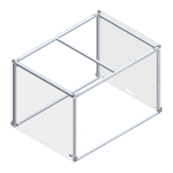
Page 3: What Is The Omio Cnc Router Enclosure
The Omio CNC Router Enclosure was designed to contain the chips that are produced by the Omio CNC Router when cutting. This makes it much safer to be used in a shop or classroom environment. The Enclosure will also help reduce some of the noise that is made while the Omio CNC Router is being used. - Page 4 Omio CNC Router Enclosure (Base) - User Guide (Rev 1) Recommended Tools Picture Name Dead Blow Hammer Allen Set Table of Contents Page 4 wcproducts.com...
-
Page 5: Omio Cnc Router Enclosure Assembly Instructions
Omio CNC Router Enclosure (Base) - User Guide (Rev 1) Omio CNC Router Enclosure Assembly Instructions Table of Contents Page 5 wcproducts.com... -
Page 6: Step 1
Omio CNC Router Enclosure (Base) - User Guide (Rev 1) Step 1 Slide a 1” x 1” tube plug into the tube plug adapter. Then slide both into the tubing. Align the tapped holes on the sides of the tube plug with the clearance holes in the tubing. -
Page 7: Step 2
Omio CNC Router Enclosure (Base) - User Guide (Rev 1) Step 2 Place tubing on a flat surface as shown below. All #10-32 rivnuts should be facing down. Install the five #10-32 x 3/8”L BHCS screws into each tubing plug in the locations shown below. Repeat this step with the other set of tubing. There should be two identical assemblies after this step. Note: Assembly for this step will be easier if all components are placed on a table so that there is access to the side holes. -
Page 8: Step 3
Omio CNC Router Enclosure (Base) - User Guide (Rev 1) Step 3 Attach the magnet and magnet mount using the two #10-32 bolts as shown below. The 3/4”L bolt will thread into the tube plug but the 1.5”L bolt will thread into the Top Plastic Panel in a later step. -
Page 9: Step 4
Omio CNC Router Enclosure (Base) - User Guide (Rev 1) Step 4 Install the tubes as shown below using four #10-32 x 3/8”L bolts. Tube 5 will get an additional bolt on each end that will go on the bottom side of the tube and thread into the tube plug, shown in Detail A. -
Page 10: Step 5
Omio CNC Router Enclosure (Base) - User Guide (Rev 1) Step 5 Attach the Plastic Side Panel as shown using the #10-32 x 1/2”L bolts. The counter bores in the plastic panel need to face the rivnuts in the tubing. -
Page 11: Step 6
Omio CNC Router Enclosure (Base) - User Guide (Rev 1) Step 6 Attach the Plastic Top Panel as shown using the #10-32 x 1/2”L bolts. The counter bores in the plastic panel need to face the rivnuts in the tubing. -
Page 12: Step 7
Omio CNC Router Enclosure (Base) - User Guide (Rev 1) Step 7 Install the Plastic Door into the slots in the Plastic Side Panels. The front of the Side Panels can be flexed out a bit to get the door into place. Repeat for the door on the other side. Table of Contents Page 12 wcproducts.com... -
Page 13: Step 8
Tighten enough so that the 3D printed parts are tight against the plastic. Repeat this for all four corners of the Omio CNC Router Enclosure. Note: The threads of the bolts will needed to be sanded down a bit for them to fit into the bearings. -
Page 14: Step 9
Omio CNC Router Enclosure (Base) - User Guide (Rev 1) Step 9 Install the three bolts and bearings into the Bearing Top Guide, as shown below. Repeat this step for all four Bearing Top Guides (both versions). Note: The threads of the bolts will needed to be sanded down a bit for them to fit into the bearings. -
Page 15: Step 10
Omio CNC Router Enclosure (Base) - User Guide (Rev 1) Step 10 Install the assemblies from the previous step onto the assembly from Step 8 in the locations shown. Use two #10-32 x 3/4”L BHCS to attach the Bearing Top Guides in each location. -
Page 16: Step 11
Omio CNC Router Enclosure (Base) - User Guide (Rev 1) Step 11 Install the magnet into the Door Magnet Holder using the two #6-32 flat head bolts prior to installing the Door Magnet Holder to the door. Repeat for all four magnets and Holders. Use two #10-32 x 1/2”L BHCS and nuts to attach the Door Magnet Holder to the Plastic Door. -
Page 17: Step 12
Omio CNC Router Enclosure (Base) - User Guide (Rev 1) Step 12 Cut the rubber trim to the desired length to cover the bottom edge of the door. It is recommended to leave 1/4”- 1/2” gap at the end of the door uncovered so that the rubber does not rub on the side panels. -
Page 18: Installing Router Enclosure
Attach the Omio CNC Router Enclosure to the Omio CNC Router Stand using the ten #10-32 x 1.5”L BHCS. Get all bolts started before fully tightening them. Note: If the Enclosure is not being installed on the Omio CNC Router Stand, the same holes can be used to attach whatever the surface may be. -
Page 19: Kit Contents
Omio CNC Router Enclosure (Base) - User Guide (Rev 1) Kit Contents Picture Name 1” x 1” x .06” Base Kit Tubing 1” x 1” Tube Plugs Base Kit 1” x 1” Tube Plug Base Kit Sleeves Plastic Side Panel... - Page 20 Omio CNC Router Enclosure (Base) - User Guide (Rev 1) Picture Name Plastic Door Base Kit Magnets Base Kit #10-32 x 3/8”L BHCS Base Kit #10-32 x 1/2”L BHCS Base Kit #10-32 x 3/4”L BHCS Base Kit Table of Contents Page 20 wcproducts.com...
- Page 21 Omio CNC Router Enclosure (Base) - User Guide (Rev 1) Picture Name #10-32 x 1”L BHCS Base Kit #10-32 x 1.25”L BHCS Base Kit #10-32 x 1.5”L BHCS Base Kit Rubber Trim 6 ft Base Kit #6-32 x 3/8”” Flat Head...
- Page 22 Omio CNC Router Enclosure (Base) - User Guide (Rev 1) Picture Name Bearing Guide Front Base Kit Bearing Guide Back Base Kit Bearing Top Guide Base Kit Bearing Top Guide Base Kit (Mirrored) Door Magnet Holder Base Kit Table of Contents Page 22 wcproducts.com...
- Page 23 Omio CNC Router Enclosure (Base) - User Guide (Rev 1) Picture Name Tubing Magnet Holder Base Kit 0.188” ID x 0.500” OD x 0.196” WD (Radial Base Kit Bearing) Table of Contents Page 23 wcproducts.com...
-
Page 24: Revision Table
Omio CNC Router Enclosure (Base) - User Guide (Rev 1) Revision Table Revision Date Revision # Description 5/4/21 First revision created. Table of Contents Page 24 wcproducts.com...
Need help?
Do you have a question about the Omio CNC and is the answer not in the manual?
Questions and answers