Table of Contents
Advertisement
Quick Links
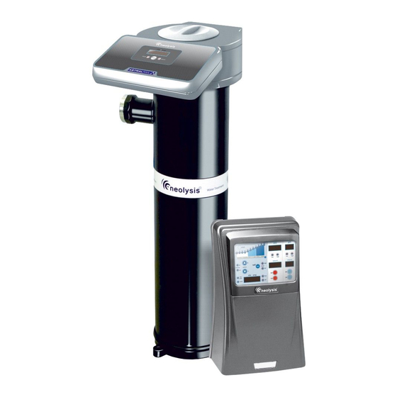
NEOLYSIS PRIVATE SYSTEM
EN
PRIVATE SYSTÈME D'NEOLYSIS
SISTEMA NEOLYSIS PRIVADO
NEOLYSIS SISTEMA PRIVATO
NEOLYSIS PRIVATE SYSTEM
NEOLYSIS SISTEMA PRIVATE
Model.
NEO-12
50
120
NEO-24
NEO-32
3
3
m
m
NEO-12 PH
5000 hr
NEO-24 PH
13000 hr
NEO-32 PH
NEO 12 +
pH
NEO 24 +
NEO 32 +
ORP
UV
INSTALLATION AND MAINTENANCE MANUAL
MANUEL D'INSTALLATION ET D'ENTRETIEN
MANUAL DE INSTALACION Y MANTENIMIENTO
MANUALE DI INSTALLAZIONE E MANUTENZIONE
EINBAU-UND BETRIEBSANLEITUNG
MANUAL DE INSTRUÇOES E MANUTENÇAO
Vers.20150129
Advertisement
Table of Contents

Summary of Contents for Neolysis NEO-12
- Page 1 NEOLYSIS PRIVATE SYSTEM PRIVATE SYSTÈME D'NEOLYSIS SISTEMA NEOLYSIS PRIVADO NEOLYSIS SISTEMA PRIVATO NEOLYSIS PRIVATE SYSTEM NEOLYSIS SISTEMA PRIVATE Model. NEO-12 NEO-24 NEO-32 NEO-12 PH 5000 hr NEO-24 PH 13000 hr NEO-32 PH NEO 12 + NEO 24 + NEO 32 + INSTALLATION AND MAINTENANCE MANUAL MANUEL D’INSTALLATION ET D’ENTRETIEN...
- Page 3 For further information regarding the points of collection of this type of wastes, please contact to the dealer where you acquired the product or to your municipal authority. For optimum performance of the Neolysis Treatment System, we recommend you to follow the instructions given below: 1. CHECK THE CONTENTS OF THE PACK:________________________________________________________ You should find the following elements inside the box: ...
- Page 4 Neolysis® treatment systems operate at 230 VAC / 50-60Hz. Do not attempt to alter the system to operate at a different voltage. Check all the electrical connectors are well tightened to avoid false contacts and their consequent overheating.
-
Page 5: Data Sheet
3. DATASHEET... - Page 7 (Fig. 1)
- Page 8 UV lamp from the sleeve (about twice the total height of the unit). It is highly recommended to install the Neolysis® system in a place of the pipe that can be easily isolated from the rest of the installation by two valves, so that the tasks of maintenance can be carried out with no need of partial or total draining of the swimming pool.
- Page 9 4.3. Electrical connections...
- Page 10 4.4. Installation of the pH / ORP sensors (only in NEO-XX PH and NEO-XX +). Insert the pH / ORP sensors into their corresponding places of the holder (Fig. 12) To that purpose, loosen the connection screws and insert the sensor into the holder. The sensors must be installed in the holder so that it is guaranteed that the sensors located in their ends are always submerged in the water circulating through the pipe.
- Page 11 [co] AUTOMATIC COVER CONTROL: input for potential-free contact. Depending on the status of the contact connected to it on the automatic cover’s electric panel, this input enables you to programme a reduction of the equipment’s output current to a percentage of its nominal value.
- Page 12 4.6. Installation of the removable control terminal (OPTIONAL) In the Neolysis® series systems it is possible to establish a remote control of the electrolysis salt system installed in the swimming pool by means of a control wall terminal installation. The interconnection between the power supply and the control terminal can be executed through a 6-conductor signal cable connected to the respective connectors in power and visualization cards.
- Page 13 4.7. Connection PoolStation...
- Page 14 1. Make sure the filter is clean to 100%, and that the pool and the installation does not contain copper, iron and algae. 2. The analytical condition of the water is very important to ensure that the Neolysis® system works with the highest levels of effectiveness. Before starting the system check that the following parameters are within the recommended levels: ...
- Page 15 5.1. UV System The UV system automatically powers the lamp once it is connected by the switch located on rear side of the control panel of the unit (see 4.3). After a few seconds, once the system detects that the lamp is ignited, the led "lamp" [19] on the control panel of the unit will stay on. The main screen [18] will show at all times the number of hours of lamp operation.
- Page 16 5.2. Electrolysis system 5.2. System on stand-by The system goes into “STAND-BY” when the “” [2] key is pressed until the “0%” light blinks. When this occurs, there is no production in the electrolysis cell (0%). Fig. 21 5.2.1. System configuration The DOMOTIC Series system can be reconfigured through a menu accessed from the control panel.
- Page 17 Fig. 23 System programming flow-sheet.
- Page 18 5.2.2. Production level selection To select the desired production level, press the “” [2] / “” [2] keys until the production level light blinks. The system information screen [17] will display the value of the production scale light [1]. The system will set its production to the desired level after a few seconds. Fig.
- Page 19 5.2.4 Integrated pH controller (modelos NEO-XX PH y NEO-XX +) The integrated pH / ORP controller is supplied with a default factory calibration and programmed with the following parameters: SETPOINT pH=”7.2” / ORP=”700 mV” IMPORTANT: In order to have a correct regulation of the pH value, the Total Alkalinity of the pool water must be maintained in the range 60–120 ppm CaCO .
- Page 20 5.2.6. ORP Setpoint prorgaming (only in models NEO-XX +) Keep the “SET” [12] key pressed until the light displays the desired ORP value within the 600 – 850 mV range. Release after selection. Fig. 27b 5.2.7 Safety stop configuration of the dosage pump (PUMP-STOP FUNCTION) The integrated pH controller has a security system (PUMP-STOP FUNCTION) acting on the dosage pump which allows to avoid the following situations: ...
- Page 21 The PUMP-STOP FUNCTION is factory set to 60 minutes. To change this value, follow the next procedure. Fig. 27d. 6. Alarms: HIGH SALT LEVEL If too much salt has been added, the production level will automatically fall beneath the selected level. The “HIGH SALT” [9] light will stay on.
- Page 22 WATER LEVEL IN CELL/FLOW DETECTOR (GAS) If an air or gas bubble forms at any time at the top of the electrolysis cell and the FLOW DETECTOR is not submerged, the system will automatically switch off production, with the “FLOW” [7] light blinking and “FLO” displayed on the system information screen [17]. The system automatically resets when water flows through the cell again or the bubble disappears.
- Page 23 The Neolysis® Series system has a light indicating malfunction of the electrolysis cell electrodes [8]. This usually occurs at the end of the electrodes ’useful life, when they lose their power. However, although this is a self-cleaning system, this malfunction could also be due to excessive scaling on the electrodes when the system operates with hard water with a high pH value.
-
Page 24: "Fast" Mode
Although all Neolysis® series salt electrolysis units are SELF-CLEANING, a prolonged operation of the system at pH values over 7.6 in waters of high hardness can produce scale formation on the surface of the electrodes. Scaling on the electrodes surface will progressively deteriorate the coating, causing a decrease of lifetime. -
Page 25: Standard Mode
2. “STANDARD” MODE “STANDARD” MODE allows the precise calibration of the pH-sensor using two calibration solutions of pH 7.0 and 4.0, however this method requires that the pH-sensor is removed from the installation. PROCEDURE: IMPORTANT: before closing the by-pass valves, stop the system from control panel (see Section 5.1). Extract the pH-sensor from the holder and wash it with tap water. -
Page 26: Error Messages
Fig. 35 ERROR MESSAGES: If the calibration process is interrupted for whatever reason, the pH-controller will automatically leave the calibration mode if the intervention of the user is not detected in a few seconds. In this case, “E1” indication in the display [15] will appear. - Page 27 Fig. 37 ERROR MESSAGES: If the calibration process is interrupted for whatever reason, the ORP controller will automatically leave the calibration mode if the intervention of the user is not detected in a few seconds. In this case, “E1” indication in display [15] will appear.
- Page 28 7.1.3. REPLACEMENT AND CLEANING THE LAMP U.V...
- Page 31 Cleaning of the quartz sleeve You should check at least once a year that the quartz sleeve does not contain any kind of deposit on its surface (lime, iron, manganese, organic matter, etc.). To do this, disconnect the system and remove the lamp as described in Section...
- Page 32 TROUBLESHOOTING: ________________________________________________________________________________________ Any action required to solve possible problems in the equipment should always be performed with the equipment disconnected from the mains. Any problem not indicated in the following list should be solved by technical service. PROBLEM SOLUTION Production indicator always indicates “0” at all production levels Check electrodes.
-
Page 33: Power Supply
9. COMPONENTS:______________________________________________________________________________ POWER SUPPLY CODE DESCRIPTION NUM. PLUS PLUS PLUS DOM00-13 Power supply cover DOM10-03 Power card AC-12 DOM18-03 Power card AC-22 DOM25-03 Power card AC-30 DOM40-03 Power card AC-7 DOM10-04 Power card AC-12/PH DOM18-04 Power card AC-22/PH DOM25-04 Power card AC-30/PH DOM40-04 Power card AC-7/PH/ORP DOM10-05... - Page 34 SENSOR HOLDER CODE DESCRIPTION NUM. PLUS PLUS PLUS R-127 Sensor holder R-035 pH-minus injection valve 3/8” * R-028 Connector PE 12 mm H-035 pH sensor R-127-01 Plug M25 H R-025 Calibration solution pH 7.0 (green) R-026 Calibration solution pH 4.0 (red) R-027 Calibration solution ORP (470 mV) RX-02...
- Page 35 OPTIONAL DETACHABLE TERMINAL (not included with the equipment) CODE DESCRIPTION NUM. PLUS PLUS PLUS DOM00-021 DOM00-022 Visualization box base DOM00-023 Cable gland M12 DOM00-024 Wall fixation DOM00-025 3x8 mm fixation screw DOM00-025 Screw joint...
-
Page 36: Technical Characteristics
10. TECHNICAL CHARACTERISTICS: TECHNICAL SPECIFICATIONS: GENERAL FEATURES: Standard working voltage Control system 230V AC – 50/60 Hz. Microprocessor. Cable: 3 x 1.0 mm , leng. 2 m. Membrane keypad with control keys NEO Series 12 0.36 A operation indication leds. NEO Series 24 0.72 A Control I/O: 3 inputs (potential-free contact type) -
Page 37: General Aspects
11. WARRANTY CONDITIONS:____________________________________________________________________ 11.1. GENERAL ASPECTS According to these provisions, the seller guarantees that the guaranteed product is in perfect condition upon delivery. 11.1.1. Total Warranty Period is 3 YEARS, except for the following components: a. LAMP: 13.000 hours or 1.000 ignitions. b. - Page 38 I.D. ELECTROQUIMICA, S.L. PRODUCTS SALT ELECTROLYSIS SYSTEM PRODUITS SYSTÈME D’ÉLECTROLYSE SALINE NEO-12 NEO-12PH NEO-12+ PRODUCTOS SISTEMA DE ELECTROLISIS DE SAL NEO-24 NEO-24PH NEO-24+ PRODOTTI SISTEMA D’ELETTROLISI SALINA NEO-32 NEO-32PH NEO-32+ PRODUKTE SALZ-ELEKTROLYSE-SYSTEM PRODUTOS SISTEMA DE ELECTRÓLISE SALINA DÉCLARATION CE DE CONFORMITÉ...
- Page 39 Made in EC 3401E100-12 NIF ES-B03731908 We reserve to change all or part of the articles or contents of this document, without prior notice Nous nous reservons le droit de modifier totalment oru en partie les caracteristiques de nos articles ou le contenu de ce document sans pré avis Nos reservamos el derecho de cambiar total o parcialmente las características de nuestros artículos o el contenido de eeste documento sin previo aviso Ci riservamo il dritto di cambiare totalemente o parzialmente le caratteristiche technique dei nostri prodotti ed il cotenuto di questo docuemntosenza nessum preavviso Wir behalten uns das recht vor die eigenschatten unserer produkte oder den inhalt dieses prospektes teilweise oder vollstanding, ohne vorherige benachichtigung zu andern...
Need help?
Do you have a question about the NEO-12 and is the answer not in the manual?
Questions and answers