Table of Contents
Advertisement
Quick Links
Advertisement
Table of Contents

Related Manuals for Rockville dBM65


Summary of Contents for Rockville dBM65
- Page 6 0.75˝ 0.75˝ (19.05mm) (19.05mm) 0.75˝ (19.05mm) 1.25˝ 1.25˝ (31.75mm) (31.75mm) USE 16 GAUGE SPEAKER WIRE...
- Page 7 Settings Adjusting the System 1. Once the system is operational, set all crossover points to the approximate settings. In the case of a basic subwoofer system, set the Low Pass Filter (LPF) crossover(s) at 100Hz or so. Set the Bass EQ to 0dB. Turn the controls using a small flathead screwdriver. Do not apply any pressure while turning as this might break the control unit. 2.
- Page 8 Settings (continued) Sealed Enclosures Sealed boxes are tuned by enclosure volume: larger enclosures tune lower; smaller enclosures tune higher. Subsonic frequencies can cause damage to your woofer as they cause it to play below the enclosure’s tuning, forcing it to the limits of its excursion and making it expend a lot of energy. To avoid damage to your woofer, set the Subsonic HPF to 25Hz – 35Hz. Ported Enclosures The enclosure’s port should be tuned to a certain frequency so that the enclosure is capable of playing all frequencies above that tuning.
-
Page 9: Input Configurations
Input Configurations 6-Channel Amp in 2-Channel Mode If your head unit has one single pair of RCA outputs, connect them to the amplifier’s channel 1 and 2 input jacks and set the Input Mode switch to 2CH. The amplifier’s preamp circuitry will automatically mix all the channels and output will occur on all 6 channels. -
Page 10: Output Configurations
Output Configurations 6-Channel Amp in 6-Channel Mode Install any combination of speakers independently on channels 1 – 6, being careful not to load any single channel below 2-ohm stereo. For typical 6˝ x 9˝ or 6.5˝ or component speaker installs, set the Crossover Mode Switches to Full Range. - Page 11 6-Channel Amp in 5-Channel Mode Channels 1 and 2 and Channels 3 and 4 should be wired to speakers with no lower than 2-ohm load per channel in stereo. Channels 5 and 6 should be bridged as per the diagram wiring the woofer to Channel 5’s positive (+) terminal and Channel 6’s negative ( –...
- Page 12 Output Configurations (continued) 6-Channel Amp in 5-Channel Mode w/Two Subwoofers Channels 1 and 2 and Channels 3 and 4 should be wired to speakers with no lower than 2-ohm load per channel in stereo. Channels 5 and 6 should be bridged as per the diagram wiring the woofers in series to Channel 5’s positive (+) terminal and Channel 6’s negative ( –...
-
Page 13: Public Address System
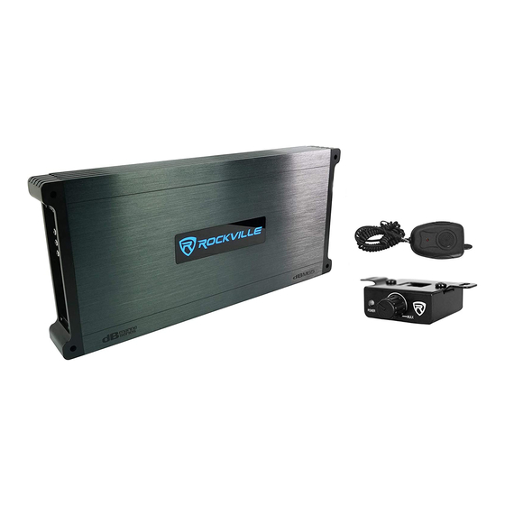
Public Address System These marine amps feature a marine public address system with microphone and talk-over functionality. Simply connect the included microphone (fig. a) to the 3.5mm jack marked MIC and you are ready to go. When the microphone is keyed, music will fade to the background. When microphone is unkeyed, music slowly fades back in. fig. - Page 14 Battery Voltage Rockville dBM Series amplifiers are rated and regulated to 13.8 volts and below. Increasing voltage to 14.4 volts will increase the power output of the amplifier in the same proportion. Maximum input voltage is 14.4 volts while the minimum voltage is 12 volts.
-
Page 15: Specifications
Additional Features • 8-Volt Preamp Circuitry • High-Speed MOSFET Power Supply • All channels on the amplifier are bridgeable • Optical Coupler Class “AB” Technology • Painted Conformal Coating PCB Board (Uses 2577 Waterproof Glue) • Studio-Grade Bipolar Output Stage Transistors •... - Page 16 SVC Configurations The minimum impedance load for a single dBM65 amp is 2-ohm stereo and 4-ohm mono bridged. Lower impedance loads will cause overheating and may damage the amp. Do not mix different impedance speakers in series and /or parallel combinations, as unequal power sharing and acoustic outputs will result.
- Page 17 DVC Configurations...
-
Page 19: Troubleshooting
Troubleshooting PROBLEM CAUSE/SOLUTION 1. Short circuit protection - Caused by the power or ground wire not being fastened tightly. Amp goes into protect mode Disconnect the speakers from the amp. If the amp is still in protect mode, you now know the issue is some- where with the power, ground, or remote wire. - Page 20 PROBLEM CAUSE/SOLUTION 1. The external fuse is not properly secured to the power wire or is not making proper contact to the wire. Amp won’t power on Ensure the fuse is properly seated and making contact. 2. Your external fuse (inside the fuse holder) is blown. Replace the fuse. Never replace the supplied external fuse with one of a larger value.
- Page 21 PROBLEM CAUSE/SOLUTION RCA signal using a multimeter. Power but no sound 4. The next thing to check is the speaker wire that is going from the amp to the speakers. If the amplifier is in bridged mode, then be sure you connected the speaker wire to the proper terminals. 5.
- Page 22 PROBLEM CAUSE/SOLUTION Amp is clipping 3. If the gain setting is too high, this can cause the amp to clip. The proper way to set your gain is to turn your receiver volume to 75% of the max, and then slowly turn your gain up. The second you hear any slight distortion, turn it down one notch and leave it at that setting.
- Page 23 PROBLEM CAUSE/SOLUTION 5. Noise can be picked up due to bad RCA cables. Specially the super cheap ones. We recommend doing a Distortion, background noise, test with different RCA cables. Replace the RCA cables if needed. crackling, or hissing in the 6.
- Page 24 PROBLEM CAUSE/SOLUTION Amp keeps blowing fuses Distribution Block Amp Fuse - If both sides of the main fuse have power, and one side of the distribution block has power, but the other side of that fuse is dead, then you’re either dealing with a shorted power wire or an internal amplifier fault.
- Page 25 PROBLEM CAUSE/SOLUTION 1. This situation happens when you connect the remote turn-on wire to a constant 12V power wire (often this Amp or powered sub does is a yellow wire) instead of to the remote turn-on wire of your receiver’s wire harness. Pull out your receiver not turn off when you turn off and plug the amplifier’s remote turn-on wire into the proper remote turn-on terminal of your receiver’s wire the vessel...
-
Page 26: Installation Notes
Installation Notes... - Page 28 © 2021 ROCKVILLE // Features and specifications are subject to change and/or improvement without notice. Though we tried our best to ensure that this manual is free and clear of errors, please don’t hold us responsible for printing errors.
Need help?
Do you have a question about the dBM65 and is the answer not in the manual?
Questions and answers