
Related Manuals for molex SST-DN4-104-1

Summary of Contents for molex SST-DN4-104-1
- Page 1 SST-DN4-104-1 and SST-DN4-104-2 Hardware Reference Guide Document Edition: 1.1 Document #: 715-0099...
- Page 2 SST-DN4-104-1 and SST-DN4-104-2 Document Edition: 1.1 Date: August 8, 2008 This document applies to the SST-DN4-104-1 and SST-DN4-104-2 interface cards. ©2008 Woodhead Industries Inc. All rights reserved. This document and its contents are the proprietary and confidential property of Woodhead Industries Inc.
-
Page 3: Table Of Contents
SST-DN4-104-1 and SST-DN4-104-2 Hardware Reference Guide Contents Preface ......................... vii Purpose of this Guide ....................... viii Using this Guide ........................viii Conventions ..........................ix Style............................ix Terminology ..........................x Special Notation ........................xi Card Overview ......................13 1.1 Warnings and Cautions......................14 1.2 Card Features........................15... - Page 4 Hardware Reference Guide SST-DN4-104-1 and SST-DN4-104-2 Hardware Registers..................... 31 3.1 DN4 Card Configuration Registers ..................32 3.1.1 Host Register Layout......................32 3.1.2 Control Register ......................33 3.1.3 AddrMatch Register .......................34 3.1.4 WinSize Register......................37 3.1.5 Bank Address Register ....................38 3.1.6 HostIrq Register ......................40 3.1.7 LedReg Register......................42 3.1.8 Reserved Register......................43...
- Page 5 SST-DN4-104-1 and SST-DN4-104-2 Hardware Reference Guide E.3 Technical Support ........................66 E.3.1 Getting Help........................67 Index..........................69 Downloaded from StockCheck.com Contents ©2008 Woodhead Industries Inc. Document Edition: 1.1, Document #: 715-0099, Template Edition: 1.1, Template #: QMS-06-045 Use, duplication or disclosure of this document or any of the information contained herein is subject to the restrictions on page ii of this document.
- Page 6 Hardware Reference Guide SST-DN4-104-1 and SST-DN4-104-2 Downloaded from StockCheck.com Contents ©2008 Woodhead Industries Inc. Document Edition: 1.1, Document #: 715-0099, Template Edition: 1.1, Template #: QMS-06-045 Use, duplication or disclosure of this document or any of the information contained herein is subject to the restrictions on page ii of this document.
-
Page 7: Preface
SST-DN4-104-1 and SST-DN4-104-2 Hardware Reference Guide Preface Preface Sections: Purpose of this Guide • Using this Guide • Conventions • Downloaded from StockCheck.com Preface ©2008 Woodhead Industries Inc. Document Edition: 1.1, Document #: 715-0099, Template Edition: 1.1, Template #: QMS-06-045... -
Page 8: Purpose Of This Guide
This guide contains technical and product-related information on the SST-DN4-104-1 and SST-DN4-104-2 network interface cards. The SST-DN4-104-1 consists of a single DeviceNet network interface (or channel), and the SST-DN4-104-2 comprises two independent interfaces, controlled by independent CPUs. Each CPU executes downloadable application firmware modules, which enable application-level product behavior. -
Page 9: Conventions
SST-DN4-104-1 and SST-DN4-104-2 Hardware Reference Guide Conventions This guide uses stylistic conventions, special terms, and special notation to help enhance your understanding. Style The following stylistic conventions are used throughout this guide: Bold indicates field names, button names, tab names, executable files,... -
Page 10: Terminology
SST-DN4-104-1 and SST-DN4-104-2 Terminology The following special terms are used throughout this guide: Card The SST-DN4-104-1 or SST-DN4-104-2 network interface card Channel A DeviceNet network interface on the card Firmware Module The embedded software module that gets loaded to the card’s memory and runs on the card. -
Page 11: Special Notation
SST-DN4-104-1 and SST-DN4-104-2 Hardware Reference Guide Special Notation The following special notations are used throughout this guide: Warning Warning messages alert the reader to situations where personal injury may result. Warnings are accompanied by the symbol shown, and precede the topic to which they refer. - Page 12 Hardware Reference Guide SST-DN4-104-1 and SST-DN4-104-2 Downloaded from StockCheck.com Preface ©2008 Woodhead Industries Inc. Document Edition: 1.1, Document #: 715-0099, Template Edition: 1.1, Template #: QMS-06-045 Use, duplication or disclosure of this document or any of the information contained herein is subject to the restrictions on page ii of this document.
-
Page 13: Card Overview
SST-DN4-104-1 and SST-DN4-104-2 Hardware Reference Guide Card Overview Chapter Sections: Warnings and Cautions • Card Features • Byte Ordering • DN4 Compatibility • Hardware Description • Downloaded from StockCheck.com Card Overview ©2008 Woodhead Industries Inc. Document Edition: 1.1, Document #: 715-0099, Template Edition: 1.1, Template #: QMS-06-045... -
Page 14: Warnings And Cautions
Hardware Reference Guide SST-DN4-104-1 and SST-DN4-104-2 1.1 Warnings and Cautions The card is an electrical component and must be treated with the following precautions: Warning Only qualified electrical personnel familiar with the construction/ operation of this equipment and the hazards involved should install, adjust, operate, and/or service this equipment. -
Page 15: Card Features
SST-DN4-104-1 and SST-DN4-104-2 Hardware Reference Guide 1.2 Card Features The card is a PC/104 interface for communication with DeviceNet and other CAN-based networks. The main features of each channel are: 16-bit PC/104 interface (compliant with PC/104, specification 2.4). Sixteen bits is the •... -
Page 16: Hardware Description
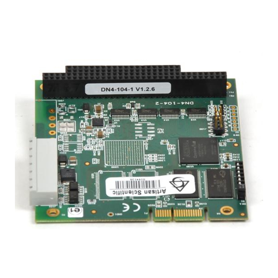
The main features of the card are described in more detail in the following sections. For information on card dimensions, refer to Section B.1, Technical Specifications. Figure 1: SST-DN4-104-1 & 2 Interface Card Table 1: Card Features Feature Description Feature... -
Page 17: Can Connector
SST-DN4-104-1 and SST-DN4-104-2 Hardware Reference Guide 1.5.1 CAN Connector The 5-pin connector is a removable connector that conforms to the standard DeviceNet pinout. Pin numbers, names and color codes are identified in the figure below. Figure 2: 5-Pin CAN Connector... - Page 18 Hardware Reference Guide SST-DN4-104-1 and SST-DN4-104-2 1.5.1.2 CANH, CANL These are the CAN communication bus signal terminals. Use only shielded twisted pair cable. When using the card on DeviceNet with DeviceNet approved cabling, these wires will already be a twisted pair with the proper DeviceNet impedance.
-
Page 19: Leds
SST-DN4-104-1 and SST-DN4-104-2 Hardware Reference Guide 1.5.2 LEDs There are three LEDs per channel: Power (PWR), Health (HLTH) and Communications (COMM). Note For information on troubleshooting using LEDs, refer to Section 4.1, HLTH or PWR LED is Red. 1.5.2.1 PWR LED The PWR LED indicates whether or not power is applied to the CAN connector. - Page 20 Hardware Reference Guide SST-DN4-104-1 and SST-DN4-104-2 1.5.2.2 HLTH LED The HLTH LED indicates the channel’s health status. This LED’s behavior is described in the following table: Table 3: HLTH LED Behavior Color Status Card initialization failed or the card is not powered...
-
Page 21: Switches
SST-DN4-104-1 and SST-DN4-104-2 Hardware Reference Guide 1.5.3 Switches Each channel’s I/O base address is set via a 6-position switch. Figure 3: Switch Positions Note Each channel uses 8 I/O addresses. For example, on the 2-channel card, selecting I/O addresses 228 and 250 actually uses 228 through 22F and 250 through 257. - Page 22 Hardware Reference Guide SST-DN4-104-1 and SST-DN4-104-2 Table 4: Switch Settings A “1” in the following table indicates that a switch is on (or UP), and a “0” indicates that a switch is off (or DOWN). The arrow on the switch (refer to Figure 3:...
- Page 23 SST-DN4-104-1 and SST-DN4-104-2 Hardware Reference Guide Channel Remarks Base Address Hex 0x618 0x620 0x628 0x630 0x638 0x640 0x648 0x650 0x658 0x660 0x668 0x670 0x678 LPT2 0x680 0x688 0x690 0x698 0x6A0 0x6A8 0x6B0 0x6B8 0x6C0 0x6C8 0x6D0 0x6D8 0x6E0 0x6E8 COM4...
- Page 24 Hardware Reference Guide SST-DN4-104-1 and SST-DN4-104-2 Downloaded from StockCheck.com Card Overview ©2008 Woodhead Industries Inc. Document Edition: 1.1, Document #: 715-0099, Template Edition: 1.1, Template #: QMS-06-045 Use, duplication or disclosure of this document or any of the information contained herein is subject to the restrictions on page ii of this document.
-
Page 25: Installation
SST-DN4-104-1 and SST-DN4-104-2 Hardware Reference Guide Installation Chapter Sections: System Requirements • Handling Precautions • Installing the Card • Connecting to a Network • Downloaded from StockCheck.com Installation ©2008 Woodhead Industries Inc. Document Edition: 1.1, Document #: 715-0099, Template Edition: 1.1, Template #: QMS-06-045... -
Page 26: System Requirements
Hardware Reference Guide SST-DN4-104-1 and SST-DN4-104-2 2.1 System Requirements To install and operate the card, the following system requirements must be met: Minimum 8K window in host memory map (default is 16K) • An available PC/104 slot • If interrupts are required, you will need a physical interrupt for each channel on which •... -
Page 27: Installing The Card
SST-DN4-104-1 and SST-DN4-104-2 Hardware Reference Guide 2.3 Installing the Card To install the card in your computer: 1. Ensure that all power to the computer is off. 2. Adequately ground yourself, as cautioned in Section 2.2, Handling Precautions. 3. Unplug the power cord, modem (if applicable), and any network cables. -
Page 28: Connecting To A Network
Hardware Reference Guide SST-DN4-104-1 and SST-DN4-104-2 2.4 Connecting to a Network This section consists of two parts: connecting to a DeviceNet network, and connecting to a CAN network. 2.4.1 Connecting to a DeviceNet Network Connect either a DeviceNet Trunk or Drop cable to the 5-pin connector, according to the color code in Section 1.5.1,... -
Page 29: Connecting To A Can Network
SST-DN4-104-1 and SST-DN4-104-2 Hardware Reference Guide 2.4.2 Connecting to a CAN Network Connect the CAN cable to the 5-pin connector and tighten all screws. Make sure that all strands of wire go into the connector, as bent strands may cause shorts to an adjacent terminal. - Page 30 Hardware Reference Guide SST-DN4-104-1 and SST-DN4-104-2 Downloaded from StockCheck.com Installation ©2008 Woodhead Industries Inc. Document Edition: 1.1, Document #: 715-0099, Template Edition: 1.1, Template #: QMS-06-045 Use, duplication or disclosure of this document or any of the information contained herein is subject to the restrictions on page ii of this document.
-
Page 31: Hardware Registers
SST-DN4-104-1 and SST-DN4-104-2 Hardware Reference Guide Hardware Registers Chapter Sections: DN4 Card Configuration Registers • Downloaded from StockCheck.com Hardware Registers ©2008 Woodhead Industries Inc. Document Edition: 1.1, Document #: 715-0099, Template Edition: 1.1, Template #: QMS-06-045 Use, duplication or disclosure of this document or any of the information contained herein is subject to the restrictions on page ii of this document. -
Page 32: Dn4 Card Configuration Registers
Hardware Reference Guide SST-DN4-104-1 and SST-DN4-104-2 3.1 DN4 Card Configuration Registers This section provides hardware register details for the card. 3.1.1 Host Register Layout Each channel has its own set of registers, located in I/O space. The base I/O address is set via the switch for that channel. -
Page 33: Control Register
This bit indicates and controls whether or not the channel’s shared memory will respond to host memory accesses. This may be used to multiplex several SST-DN4-104-1 or SST-DN4-104-2 cards or channels at the same base address, by enabling the memory on one channel at a time. -
Page 34: Addrmatch Register
Hardware Reference Guide SST-DN4-104-1 and SST-DN4-104-2 Bit Name Description • Reading 0 indicates interrupt complete 3.1.3 AddrMatch Register This register controls the channel’s base memory address in host memory space. Each channel may be at a different address. If two channels are used at the same address, use MemEn to turn on one channel at a time. - Page 35 SST-DN4-104-1 and SST-DN4-104-2 Hardware Reference Guide Bit and Value Address AM19 AM18 AM17 AM16 AM15 AM14 AM13 AM12 0x9E 0x9E000 0xA0 0xA0000 0xA2 0xA2000 0xA4 0xA4000 0xA6 0xA6000 0xA8 0xA8000 0xAA 0xAA000 0xAC 0xAC000 0xAE 0xAE000 0xB0 0xB0000 0xB2 0xB2000...
- Page 36 Hardware Reference Guide SST-DN4-104-1 and SST-DN4-104-2 Bit and Value Address AM19 AM18 AM17 AM16 AM15 AM14 AM13 AM12 0xF4 0xF4000 0xF6 0xF6000 0xF8 0xF8000 0xFA 0xFA000 0xFC 0xFC000 0xFE 0xFE000 Table 10: AddrMatch Register Bit Descriptions Description Bit Name AM19-AM12 represent the upper address match required to decode memory.
-
Page 37: Winsize Register
SST-DN4-104-1 and SST-DN4-104-2 Hardware Reference Guide 3.1.4 WinSize Register This register controls the window size by masking off the AM19-AM12 and BA19-12 bits in the AddrMatch and Bank Address registers. Table 12, WinSize Register Values, maps the WS bit values required for each valid window size. -
Page 38: Bank Address Register
Hardware Reference Guide SST-DN4-104-1 and SST-DN4-104-2 Table 13: WinSize Register Bit Descriptions Bit Name Description WS19-WS12 WS19-WS12 represent the window size, according to Table 12: Winsize Register Values. • Writing any value other than those above has no effect The size of the memory window affects the number of banks required to access all memory. - Page 39 SST-DN4-104-1 and SST-DN4-104-2 Hardware Reference Guide Bit and Value Window Size and Bank Number BA19 BA18 BA17 BA16 BA15 BA14 BA13 BA12 128k 256k * x = don’t care Table 16: Bank Address Register Bit Descriptions Description Bit Name Each channel has 256k of memory accessible to the host. The Bank Address bits select BA17-13 which bank of memory the host can access.
-
Page 40: Hostirq Register
Hardware Reference Guide SST-DN4-104-1 and SST-DN4-104-2 3.1.6 HostIrq Register This register controls how interrupts from the card are generated. Table 17: HostIrq Register Settings Name Platform Platform ID IrqLevel3 IrqLevel2 IrqLevel1 IrqLevel0 Read/Write Reset The DN4 platform supports DN3/DN4 hardware detection in the HostIrq register as follows: 1. - Page 41 SST-DN4-104-1 and SST-DN4-104-2 Hardware Reference Guide Table 18: HostIrq Register Bit Descriptions Bit Name/ Value Description IrqLevel3-IrqLevel0 These bits determine the hardware interrupt level used when interrupts are enabled and an interrupt is generated by the channel’s processor. Supported values are:...
-
Page 42: Ledreg Register
Hardware Reference Guide SST-DN4-104-1 and SST-DN4-104-2 3.1.7 LedReg Register This register reflects the state of the channel’s LEDs, allowing host software to monitor the LEDs and display them on-screen. Table 19: LedReg Register Settings HLTH COMM Name Reserved PwrRed PwrGrn... -
Page 43: Reserved Register
SST-DN4-104-1 and SST-DN4-104-2 Hardware Reference Guide 3.1.8 Reserved Register This register is reserved and must not be accessed by host applications. 3.1.9 FamilyId Register This register identifies the product family of the card. Table 21: FamilyId Register Settings Name FamilyId7... - Page 44 Hardware Reference Guide SST-DN4-104-1 and SST-DN4-104-2 Downloaded from StockCheck.com Hardware Registers ©2008 Woodhead Industries Inc. Document Edition: 1.1, Document #: 715-0099, Template Edition: 1.1, Template #: QMS-06-045 Use, duplication or disclosure of this document or any of the information contained herein is subject to the restrictions on page ii of this document.
-
Page 45: Troubleshooting
SST-DN4-104-1 and SST-DN4-104-2 Hardware Reference Guide Troubleshooting Chapter Sections: HLTH or PWR LED is Red • Memory Conflict • Card Not Found • General Troubleshooting • For a list of hardware-related errors that can be generated by the card, refer to Appendix A, Error Messages. -
Page 46: Hlth Or Pwr Led Is Red
Hardware Reference Guide SST-DN4-104-1 and SST-DN4-104-2 4.1 HLTH or PWR LED is Red This section describes strategies for troubleshooting, using a red HLTH or PWR LED. Note For information on LED flash codes, refer to Section A.3, Fatal Hardware Self-Test Flash Codes. -
Page 47: Memory Conflict
SST-DN4-104-1 and SST-DN4-104-2 Hardware Reference Guide 4.2 Memory Conflict If a memory conflict is detected, examine the resource allocations in the operating system. If the operating system does not manage resources, review the requirements of the other hardware installed in the machine to select a non-conflicting memory window. If you continue to experience difficulties, refer to Section 4.4,... - Page 48 Hardware Reference Guide SST-DN4-104-1 and SST-DN4-104-2 Downloaded from StockCheck.com Troubleshooting ©2008 Woodhead Industries Inc. Document Edition: 1.1, Document #: 715-0099, Template Edition: 1.1, Template #: QMS-06-045 Use, duplication or disclosure of this document or any of the information contained herein is subject to the restrictions on page ii of this document.
-
Page 49: Error Messages
SST-DN4-104-1 and SST-DN4-104-2 Hardware Reference Guide Error Messages Appendix Sections: Introduction • FamilyID Messages • Fatal Hardware Self-Test Flash Codes • Downloaded from StockCheck.com Error Messages ©2008 Woodhead Industries Inc. Document Edition: 1.1, Document #: 715-0099, Template Edition: 1.1, Template #: QMS-06-045... -
Page 50: Introduction
Hardware Reference Guide SST-DN4-104-1 and SST-DN4-104-2 A.1 Introduction The following errors may be reported during the card’s startup self-test. Error messages are posted in the Message Area (0x40) of the Host Interface Memory and can be displayed using one of the status applications, such as DNSTAT, provided with the card. -
Page 51: Fatal Hardware Self-Test Flash Codes
SST-DN4-104-1 and SST-DN4-104-2 Hardware Reference Guide A.3 Fatal Hardware Self-Test Flash Codes Fatal failures during startup are accompanied by an 8-bit fault code, flashed on the HLTH LED. The fault code will be output MSB first, with a 1 (one) bit shown as a green LED, and a zero (0) bit shown as a red LED. - Page 52 Hardware Reference Guide SST-DN4-104-1 and SST-DN4-104-2 Downloaded from StockCheck.com Error Messages ©2008 Woodhead Industries Inc. Document Edition: 1.1, Document #: 715-0099, Template Edition: 1.1, Template #: QMS-06-045 Use, duplication or disclosure of this document or any of the information contained herein is subject to the restrictions on page ii of this document.
-
Page 53: Technical Specifications
SST-DN4-104-1 and SST-DN4-104-2 Hardware Reference Guide Technical Specifications Appendix Sections Technical Specifications • Downloaded from StockCheck.com Technical Specifications ©2008 Woodhead Industries Inc. Document Edition: 1.1, Document #: 715-0099, Template Edition: 1.1, Template #: QMS-06-045 Use, duplication or disclosure of this document or any of the information contained herein is subject to the restrictions on page ii of this document. -
Page 54: Technical Specifications
Hardware Reference Guide SST-DN4-104-1 and SST-DN4-104-2 B.1 Technical Specifications The following tables list the technical specifications for the card. Table 24: Environmental Specifications Ambient Conditions Storage temp: -40°C to +85°C Operating temp: 0°C to 55°C Humidity: 5% to 95% non-condensing... - Page 55 SST-DN4-104-1 and SST-DN4-104-2 Hardware Reference Guide The following figure provides a detailed breakdown of the card’s dimensions. Figure 4: SST-DN4-104-1 & 2 Interface Card Dimensions Legend For information on card components, refer to Section 1.5, Hardware 1- and 2-channel Description.
- Page 56 Hardware Reference Guide SST-DN4-104-1 and SST-DN4-104-2 Downloaded from StockCheck.com Technical Specifications ©2008 Woodhead Industries Inc. Document Edition: 1.1, Document #: 715-0099, Template Edition: 1.1, Template #: QMS-06-045 Use, duplication or disclosure of this document or any of the information contained herein is subject to the restrictions on page ii of this document.
-
Page 57: Loading Firmware
SST-DN4-104-1 and SST-DN4-104-2 Hardware Reference Guide Loading Firmware Appendix Sections: Loading Firmware • Note This appendix explains how to load firmware to the card manually, or how to write your own loader. If you are using a Windows loader provided by Woodhead Software & Electronics, the following instructions are not required. -
Page 58: Loading Firmware
Hardware Reference Guide SST-DN4-104-1 and SST-DN4-104-2 C.1 Loading Firmware Firmware modules for the card are supplied as .ss4 files, found on the software CD-ROM or on the website at http://www.woodhead.com. If you are developing a driver for the card or producing a stand-alone embedded application, read the following section for details on loading a module into the channel’s memory. -
Page 59: Check For Conflicting Ram
SST-DN4-104-1 and SST-DN4-104-2 Hardware Reference Guide C.1.2 Check for Conflicting RAM Before the channel’s shared memory can be safely enabled, you must determine that no other system devices are using the intended memory address range. Note Any task switching, interrupts or processes should be disabled during this procedure. -
Page 60: Test Channel Ram
Hardware Reference Guide SST-DN4-104-1 and SST-DN4-104-2 C.1.3 Test Channel RAM To test a channel’s RAM, follow these steps: 1. Write the upper byte of the desired 20-bit base address (base address >> 12) to the AddrMatch Register. 2. Write the desired window size to the WinSize register (refer to Section 3.1.4, WinSize Register, for details). -
Page 61: Load And Start The Firmware Module
SST-DN4-104-1 and SST-DN4-104-2 Hardware Reference Guide C.1.4 Load and Start the Firmware Module To load and start the firmware module, follow these steps: 1. Write the contents of the entire firmware file into shared memory, starting at bank zero (0), offset zero (0). - Page 62 Hardware Reference Guide SST-DN4-104-1 and SST-DN4-104-2 Downloaded from StockCheck.com Loading Firmware ©2008 Woodhead Industries Inc. Document Edition: 1.1, Document #: 715-0099, Template Edition: 1.1, Template #: QMS-06-045 Use, duplication or disclosure of this document or any of the information contained herein is subject to the restrictions on page ii of this document.
-
Page 63: Ce Compliance
SST-DN4-104-1 and SST-DN4-104-2 Hardware Reference Guide CE Compliance Appendix Sections: CE Compliance • Downloaded from StockCheck.com CE Compliance ©2008 Woodhead Industries Inc. Document Edition: 1.1, Document #: 715-0099, Template Edition: 1.1, Template #: QMS-06-045 Use, duplication or disclosure of this document or any of the information contained herein is subject to the restrictions on page ii of this document. -
Page 64: Ce Compliance
Hardware Reference Guide SST-DN4-104-1 and SST-DN4-104-2 D.1 CE Compliance This device meets or exceeds the requirements of the following standards: EN 61326-1:2006: “Electrical equipment for measurement, control and laboratory use - • EMC requirements, Part 1: General Requirements. EN 55011:1998 + A1:1999 & A2:2002, Class A, Group 1 – Industrial, Scientific and •... -
Page 65: Warranty And Support
SST-DN4-104-1 and SST-DN4-104-2 Hardware Reference Guide Warranty and Support Appendix Sections: Warranty • Reference Documents • Technical Support • Downloaded from StockCheck.com Warranty and Support ©2008 Woodhead Industries Inc. Document Edition: 1.1, Document #: 715-0099, Template Edition: 1.1, Template #: QMS-06-045... -
Page 66: Warranty
Hardware Reference Guide SST-DN4-104-1 and SST-DN4-104-2 E.1 Warranty For warranty information pertaining to the card, refer to http://www.mysst.com/warranty.asp. E.2 Reference Documents The following documents provide additional details on DeviceNet and/or the card: DeviceNet Specification: CIP Library Volume 1 Ed 3.2 "Common Industrial Protocol”... - Page 67 SST-DN4-104-1 and SST-DN4-104-2 Hardware Reference Guide E.3.1 Getting Help Technical support is available during regular business hours by telephone, fax or email from any Woodhead Software & Electronics office, or from http://www.woodhead.com. Documentation and software updates are also available on the website.
- Page 68 Hardware Reference Guide SST-DN4-104-1 and SST-DN4-104-2 Other countries: Tel: +33 2 32 96 04 23 Fax: +33 2 32 96 04 21 Email: WoodheadIC.SupportEU@molex.com Asia-Pacific Japan: Tel: +81 52 221 5950 Fax: +81 46 265 2429 Email: WoodheadIC.SupportAP@molex.com Singapore: Tel: +65 6268 6868...
- Page 69 SST-DN4-104-1 and SST-DN4-104-2 Hardware Reference Guide Index status of, 19 system requirements for, 26 AddrMatch Register, 34 technical specifications for, 54 technical support for, 66 troubleshooting, 46 Bank Address Register, 38 verifying presence of, 58 byte ordering, 15 warnings for, 14, 45, 64...
- Page 70 Hardware Reference Guide SST-DN4-104-1 and SST-DN4-104-2 conventions used in this guide status of, 42 special notation, xi troubleshooting with, 46 special terms, x Host Register, 32 host, defined, x style, ix current draw, 54 HostIrq Register, 40 humidity, operating, 54...
- Page 71 SST-DN4-104-1 and SST-DN4-104-2 Hardware Reference Guide network specifications, 54 HostIrq, 40 note, defined, xi reserved, 43 WinSize, 37 requirements, system, 26 Reserved register, 43 operating temperature, 54 settings power for jumpers, 21 external, 54 for switches, 21 for CAN network, 29...
- Page 72 Hardware Reference Guide SST-DN4-104-1 and SST-DN4-104-2 radio interference, 64 warnings warranty, 66 card handling, 14 wattage, typical, 54 width, of card, 54 defined, xi emergency stop circuit, 14 WinSize Register, 37 installation, 45 wrist strap, 26 Downloaded from StockCheck.com Index ©2008 Woodhead Industries Inc.
Need help?
Do you have a question about the SST-DN4-104-1 and is the answer not in the manual?
Questions and answers