Table of Contents

Summary of Contents for Thermo geotech MIE pDR-1500
- Page 1 MIE pDR-1500 Instruction Manual Active Personal Particulate Monitor Part Number 105983-00 4Oct2011 For Sales & Service Contact 2650 E. 40th Ave. • Denver, CO 80205 Phone 303-320-4764 • Fax 303-322-7242 1-800-833-7958 www.geotechenv.com...
- Page 2 © 2008 Thermo Fisher Scientific Inc. All rights reserved. Specifications, terms and pricing are subject to change. Not all products are available in all countries. Please consult your local sales representative for details. Thermo Fisher Scientific Air Quality Instruments 27 Forge Parkway...
- Page 3 Further information on Thermo Fisher Scientific’s compliance with these Directives, the recyclers in your country, and information on Thermo Fisher Scientific products which may assist the detection of substances subject to the RoHS Directive are available at: www.thermo.com/WEEERoHS.
- Page 5 Appendix A “Warranty” provides a copy of the warranty statement. Appendix B “Serial Commands” provides a list of the serial port commands that can be used to remotely control the instrument. Thermo Fisher Scientific MIE pDR-1500 Instruction Manual...
- Page 6 AC power ▲ supply. To operate the unit outdoors, provisions should be made to protect it from environmental extremes outside its specified range, and from any exposure to precipitation. ▲ MIE pDR-1500 Instruction Manual Thermo Fisher Scientific...
- Page 7 Marking of electrical and electronic equipment which applies to electrical and electronic equipment falling under the Directive 2002/96/EC (WEEE) and the ▲ equipment that has been put on the market after 13 August 2005. Thermo Fisher Scientific MIE pDR-1500 Instruction Manual...
- Page 8 Where to Get Help Service is available from exclusive distributors worldwide. Contact one of the phone numbers below for product support and technical information or visit us on the web at www.thermo.com/aqi. 1-866-282-0430 Toll Free 1-508-520-0430 International MIE pDR-1500 Instruction Manual...
-
Page 9: Table Of Contents
Keypad and Screen Cursor Functions and Operation ......3-3 Key Press Functions ................. 3-4 Startup ..................... 3-5 Operate Menu..................3-6 Start A Run ..................3-6 Concentration/Scattering .............. 3-6 Elapsed Time ................3-7 Maximum Run Reading..............3-7 STEL .................... 3-7 Battery/Memory................3-8 Thermo Fisher Scientific MIE pDR-1500 Instruction Manual... - Page 10 Analog Output Edit ..............3-20 LCD Backlight................3-21 LCD Backlight Edit ..............3-21 LCD Contrast................3-22 LCD Contrast Edit ..............3-22 Time/Date ..................3-22 Time/Date Edit................3-22 Calibrate Menu ................. 3-24 Temperature Offset................ 3-24 MIE pDR-1500 Instruction Manual Thermo Fisher Scientific...
- Page 11 Chapter 7 Outputs and Alarm .................... 7-1 Analog Signal Output ................. 7-2 Alarm Description and Operation............7-3 Alarm Connection................7-4 Real-time RS-232 Output..............7-6 Serial Communications Protocols............7-7 Chapter 8 Optional Accessories..................8-1 Thermo Fisher Scientific MIE pDR-1500 Instruction Manual...
- Page 12 Contents Appendix A Warranty......................A-1 Serial Commands .....................B-1 Appendix B viii MIE pDR-1500 Instruction Manual Thermo Fisher Scientific...
- Page 13 Figure 4–1. Cyclone D50 Curves................. 4-5 Figure 5–1. Filter Assembly Location – turn counter-clockwise to open ..5-6 Figure 5–2. Filter Cassette Assembly – Snap Rings and Filter......5-7 Figure 7–1. pDR-1500 External Alarm Driver ............. 7-4 Thermo Fisher Scientific MIE pDR-1500 Instruction Manual...
- Page 14 Figures MIE pDR-1500 Instruction Manual Thermo Fisher Scientific...
- Page 15 Tables Table 1–1. MIE pDR-1500 Specifications............1-4 Table 5–1. pDR-1500 Replacement Parts............5-3 Table 6–1. Troubleshooting – Error Code Responses from Zeroing ....6-2 Thermo Fisher Scientific MIE pDR-1500 Instruction Manual...
- Page 16 Tables MIE pDR-1500 Instruction Manual Thermo Fisher Scientific...
-
Page 17: Chapter 1 Introduction
● “Specifications” on page ● Thermo Fisher Scientific is pleased to supply this active personal particulate monitor. We are committed to the manufacture of instruments exhibiting high standards of quality, performance, and workmanship. Service personnel are available for assistance with any questions or problems that may arise in the use of this monitor. -
Page 18: General Description
LCD screen, such as run start time and date, time averaged concentration, elapsed run time, maximum and STEL values with times of occurrence, battery voltage, data storage memory, temperature, RH, volumetric flow rate, barometric pressure, etc. MIE pDR-1500 Instruction Manual Thermo Fisher Scientific... - Page 19 (e.g., Microsoft Excel™, Lotus 1-2-3™, etc.). The pDR-1500 combines, easy to use menu-driven software, and advanced diagnostics to offer unsurpassed flexibility and reliability. The pDR-1500 specifications follow. Thermo Fisher Scientific MIE pDR-1500 Instruction Manual...
-
Page 20: Specifications
RH correction setting, max. conc., time of max. conc., max. STEL, time of max. STEL, avg. conc., alarm on/off, alarm threshold, error codes, inlet setting, flow rate setting and site name MIE pDR-1500 Instruction Manual Thermo Fisher Scientific... - Page 21 Whatman type 1827 037 (with 1.5 μm pore size filter) NIOSH Methods 0500 and 0600 use Millipore type PVC5 037 00 (with 5 μm pore size filter) and a GK 2.05 Cyclone. Service Filter Integrated HEPA filter for background zeroing Thermo Fisher Scientific MIE pDR-1500 Instruction Manual...
- Page 22 Introduction Notes: Referred to gravimetric calibration with SAE Fine (ISO Fine) test dust (mmd = 2 to 3 μm, g = 2.5, as aerosolized) At constant temperature and full battery voltage User selectable MIE pDR-1500 Instruction Manual Thermo Fisher Scientific...
-
Page 23: Chapter 2 Guidelines And Instrument Layout
● Positioning on page ● Air Sampling Guidelines on page ● Instrument Layout on page ● Environmental Constraints and Certifications on page 2-15 ● Communications with Computer on page 2-16 ● Thermo Fisher Scientific MIE pDR-1500 Instruction Manual... -
Page 24: Unpacking And Parts Identification
● Zeroing/recirculation tubing ● Zeroing filter ● Instruction manual ● If any parts are missing, contact Thermo Fisher Scientific immediately. *One of each is installed in the instrument at the time of shipping MIE pDR-1500 Instruction Manual Thermo Fisher Scientific... -
Page 25: Handling
Re-zeroing is recommended. WARNING Whenever the pDR-1500 is shipped, care should be taken in placing it in its carrying case and repackaging it with the original factory provided packaging. ▲ Thermo Fisher Scientific MIE pDR-1500 Instruction Manual... -
Page 26: Safety
▲ If the pDR-1500 is to be worn on an individual, please be sure that the ● belt clip is secured properly, or the pDR-1500 is secured firmly within a sufficient carrying device. MIE pDR-1500 Instruction Manual Thermo Fisher Scientific... -
Page 27: Positioning
However, if the duct or chamber that an extracted sample is being drawn from is of an excessive vacuum, the pDR-1500 may not be appropriate for this purpose. Thermo Fisher Scientific MIE pDR-1500 Instruction Manual... -
Page 28: Air Sampling Guidelines
For tubing lengths of up to 2 m (6 ft), 6 mm ID (1/4 in. ID) plastic ● tubing with wall thickness of 1/16 in. is a practical size which can be stretched over the pDR-1500 inlet stem. MIE pDR-1500 Instruction Manual Thermo Fisher Scientific... -
Page 29: Instrument Layout
Figure 2–5. All related functions are externally accessible. Qualified Thermo Fisher Scientific personnel should perform all repair and maintenance. Please contact the factory if any problem should arise. Do not attempt to disassemble the pDR-1500, except as described in Chapter “Maintenance and... -
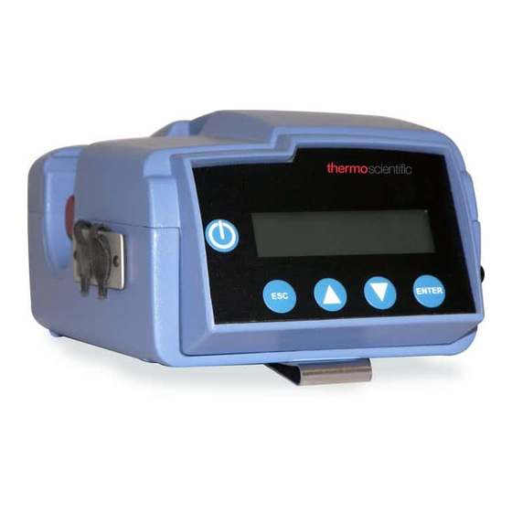
Page 30: Front Panel
When operating from the internal battery, the screen backlighting is disabled in order to conserve power. Refer to Figure 2–1 for location of controls and display below. Figure 2–1. Front Display MIE pDR-1500 Instruction Manual Thermo Fisher Scientific... -
Page 31: Rear Power Port
Refer to Figure 2–2 below for the location of items on the rear panel of the pDR-1500. Figure 2–2. Rear Power Port Thermo Fisher Scientific MIE pDR-1500 Instruction Manual... -
Page 32: Side Pm Inlet, Usb, Rs232/Analog
1500. Refer to Figure 2–3 below for the location of items on the Side PM Inlet, USB, RS232/Analog Panel of the pDR-1500. Figure 2–3. Side PM Inlet, USB, RS-232/Analog Panel 2-10 MIE pDR-1500 Instruction Manual Thermo Fisher Scientific... -
Page 33: Side Filter Assembly And Exhaust
(e.g., NIOSH 0600) and speciation. Refer to Figure 2–4 below for the location of items on the Side Filter Assembly and Exhaust Port Panel of the pDR-1500. Figure 2–4. Side Filter Assembly and Exhaust Thermo Fisher Scientific MIE pDR-1500 Instruction Manual 2-11... -
Page 34: Bottom Battery And Belt Clip
The second feature to be pointed out is the belt clip, which is to be used for personal aerosol monitoring. Refer to Figure 2–5 below for the location of items on the Bottom Battery Door and Belt Clip Panel. Figure 2–5. Bottom Battery Door and Belt Clip 2-12 MIE pDR-1500 Instruction Manual Thermo Fisher Scientific... -
Page 35: Preparation For Operation
Equipment Damage Please note that the important purpose of this filter cassette is to protect the pump. ▲ However, these filters can double as gravimetric filters and/or speciation collection filters. Thermo Fisher Scientific MIE pDR-1500 Instruction Manual 2-13... -
Page 36: Electrical Connections
If AC power is not available and continuous operation over more than 20 hours is required, please consult with Thermo Fisher Scientific for a Technical Note regarding the use of an external battery or other DC source (e.g., solar power). -
Page 37: Environmental Constraints And Certifications
CAN/CSA C22.2 No. 61010-1:2004 2 Edition, Safety Requirements ● for Electrical Equipment for Measurement, Control and Laboratory Use – Part 1: General Requirements CENELEC EN 61326-1 ● FCC 47 CFR 15B cIA ● Thermo Fisher Scientific MIE pDR-1500 Instruction Manual 2-15... -
Page 38: Communications With Computer
● USB communications cable ● Software CD (pDR Port) ● Software To install the Thermo Scientific provided software (pDR Port) in the computer, proceed as follows: Installation Procedure Insert the CD labeled pDR Port into the computer ● The install program should start automatically ●... - Page 39 400 mg/m Analog output status (enabled or disabled) ● Alarm level (0.001 to 400.0 mg/m , in 1-μg/m increments) ● Alarm status (enabled or disabled) ● Humidity correction (enabled or disabled) ● Thermo Fisher Scientific MIE pDR-1500 Instruction Manual 2-17...
- Page 40 Tag (data file) to be loaded or deleted. In the image below, the “Delete all data” box appears with a check mark. By selecting this box and clicking on Delete, all tag files can be deleted at once. 2-18 MIE pDR-1500 Instruction Manual Thermo Fisher Scientific...
- Page 41 In this second image of the Data Text tab, it shows a Tag File loaded to the window. The data can now be viewed in the Data Graph tab and saved as a CSV file. Thermo Fisher Scientific MIE pDR-1500 Instruction Manual 2-19...
- Page 42 To review the parameter values currently programmed into the pDR-1500, click on Get current configuration. After editing the parameters, click on Set new configuration to input the newly selected values into the pDR- 1500. 2-20 MIE pDR-1500 Instruction Manual Thermo Fisher Scientific...
- Page 43 Site List. This tab allows the user to retrieve, edit, and set the site list for the instrument. Site lists may also be read and written to a file on a computer. Thermo Fisher Scientific MIE pDR-1500 Instruction Manual 2-21...
-
Page 45: Chapter 3 Operation
“Keypad and Screen Cursor Functions and Operation” on page ● “Operate Menu” on page ● “Configure Menu” on page 3-14 ● “Calibrate Menu” on page 3-24 ● “Starting a Run” on page 3-28 ● Thermo Fisher Scientific MIE pDR-1500 Instruction Manual... -
Page 46: Operating Modes
HEPA filter. 5. Shutdown. Accomplished by holding the ON/OFF key until text on screen is no longer visible. The instrument is off. MIE pDR-1500 Instruction Manual Thermo Fisher Scientific... -
Page 47: Keypad And Screen Cursor Functions And Operation
Analog Output Logging Period Edit Analog Output Edit Logging Site Edit LCD Backlight Logging Tag Number LCD Backlight Edit Battery/Memory Status LCD Contrast LCD Contrast Edit Time/Date Time/Date Edit Figure 3–1. Keypad Overview Thermo Fisher Scientific MIE pDR-1500 Instruction Manual... -
Page 48: Key Press Functions
UP ( ▲ ) scrolls through menu displays that are in a circular list (in a ● backward direction) or scrolls through values (also in a backward direction) in a display that is not part of a list (an edit display). MIE pDR-1500 Instruction Manual Thermo Fisher Scientific... -
Page 49: Startup
This screen appears for three seconds upon initiation of a power-up sequence, then default directly to the Operate Menu screen. In this screen you may scroll up or down to the Calibrate Menu or Configure Menu, respectively. Thermo Fisher Scientific MIE pDR-1500 Instruction Manual... -
Page 50: Operate Menu
The real-time concentration is an average taken over a time interval called “Display Time”, which is programmed by the user. The presence of the asterisk (*) in the first line indicates that data logging is enabled. MIE pDR-1500 Instruction Manual Thermo Fisher Scientific... -
Page 51: Elapsed Time
▲ or From the Start a Run screen, press the ENTER ● ▼ key to the Stel screen or press the key to stop a run. Thermo Fisher Scientific MIE pDR-1500 Instruction Manual... -
Page 52: Stel
▲ or From the Start a Run screen, press the ENTER ● ▼ key to the Flow/Pres screen or press the key to stop a run. FLOW 2.000 LPM PRES 750 mmHg MIE pDR-1500 Instruction Manual Thermo Fisher Scientific... -
Page 53: Stop Run
▲ or ▼ From the Operate menu, press the ENTER ● key to the Start@ screen. Thermo Fisher Scientific MIE pDR-1500 Instruction Manual... -
Page 54: Start Time/Date Edit
From the Operate menu, press the ENTER ● key to the Zero Instrument screen. Note Do not zero through the red or blue sharp-cut cyclones. Only zero through a clean Total Inlet. ▲ 3-10 MIE pDR-1500 Instruction Manual Thermo Fisher Scientific... -
Page 55: Zero In Progress
3 seconds, displays site label for 3 seconds, and tag number for 3 seconds in sequence. key and scroll the ▲ or ▼ From the Operate menu, press the ENTER ● key to the Logging screen. Thermo Fisher Scientific MIE pDR-1500 Instruction Manual 3-11... -
Page 56: Logging Status Edit
The Logging Site Edit screen allows the user to select from the list of 50 logging sites. Each site has three associated values: Site Number, a Site Name, and a Calibration Factor. The Site Name is the only value displayed 3-12 MIE pDR-1500 Instruction Manual Thermo Fisher Scientific... -
Page 57: Logging Site Edit
Status key and scroll the ▲ or ▼ From the Operate menu, press the ENTER ● key to the Battery/Memory screen. BATTERY 12.6V MEMORY LEFT Thermo Fisher Scientific MIE pDR-1500 Instruction Manual 3-13... -
Page 58: Display Average Time
ENTER ● display averaging time. Press the key to save the display averaging time and return to ENTER ● Display Avg Time screen. DISPLAY AVG TIME 11 seconds 3-14 MIE pDR-1500 Instruction Manual Thermo Fisher Scientific... -
Page 59: Flow Rate Edit
3 seconds in sequence. key and scroll the ▲ or ▼ From the Configure menu, press the ENTER ● key to the Logging screen. LOGGING ENABLED 1:00:00 h:m:s LOGGING ENABLED Factory default Thermo Fisher Scientific MIE pDR-1500 Instruction Manual 3-15... -
Page 60: Logging Status Edit
The site numbers are in range (1, 2, 3..., 50), the site names and calibration factors are editable only by external serial command. The asterisk (*) appears to the left of the field being edited. 3-16 MIE pDR-1500 Instruction Manual Thermo Fisher Scientific... -
Page 61: Logging Site Edit
From the Inlet Type screen, press the key to edit the inlet type. ENTER ● Press the key to save the inlet type and return to the Inlet Type ENTER ● screen. Thermo Fisher Scientific MIE pDR-1500 Instruction Manual 3-17... -
Page 62: Rh Correction
15 minute rolling (boxcar) average is higher than the STEL alarm level setting. Each of the two enabled alarm options use separately stored alarm level values. 3-18 MIE pDR-1500 Instruction Manual Thermo Fisher Scientific... -
Page 63: Alarm Option Edit
Units The Units screen allows the selection of units from micrograms per cubic meter (μg/m ) or to a measure of the aerosol scattering coefficient in units of inverse mega meters (1/Mm). Thermo Fisher Scientific MIE pDR-1500 Instruction Manual 3-19... -
Page 64: Units Edit
100/Mm, 1000/Mm, 10000/Mm, and 100000/Mm. The values offered for μg/M (concentration) are: disabled, 0.10 mg/m , 0.40 mg/m , 1.00 mg/m , 4.00 mg/m , 10.0 mg/m , 40 mg/m , 100 mg/m , 400 mg/m , and 3-20 MIE pDR-1500 Instruction Manual Thermo Fisher Scientific... -
Page 65: Lcd Backlight
From the LCD Backlight screen, press the key to edit the LCD ENTER ● backlight. Press the key to save the LCD backlight status and return to the ENTER ● LCD Backlight screen. LCD BACKLIGHT * ENABLED Thermo Fisher Scientific MIE pDR-1500 Instruction Manual 3-21... -
Page 66: Lcd Contrast
The Time/Date Edit screen allows the user to edit the current time and date. The Start Time/Date Edit screen allows the user to edit the delayed start time and date. In the display, the and the keys provide ENTER 3-22 MIE pDR-1500 Instruction Manual Thermo Fisher Scientific... - Page 67 From the Time/Date screen, press the key to and to advance to ENTER ● edit the next field. Press the key to save the time/date and return to the Time/Date ENTER ● screen. TIME *15:59:41 13-Nov-09 Thermo Fisher Scientific MIE pDR-1500 Instruction Manual 3-23...
-
Page 68: Calibrate Menu
Offset screen. TEMP OFFSET * 0.1 22.2 C Please note that a precise and accurate calibration of the RH-sensor is critical to maintaining precision between collocated devices when using RH Correction enabled. 3-24 MIE pDR-1500 Instruction Manual Thermo Fisher Scientific... -
Page 69: Pressure Offset
The RH Offset Edit screen allows the user to edit the RH offset. Use the ▲ and ▼ keys to increase or decrease the RH offset in increments of 0.1% RH. The asterisk (*) appears to the left of the field being edited. Thermo Fisher Scientific MIE pDR-1500 Instruction Manual 3-25... -
Page 70: Flow Rate Calibration
In the following screen there are two values shown; ADJ = 188 and LPM = 1.00. In this screen the 188 is the pump speed control value used to achieve 1.00 L/min. The user may adjust the motor speed to achieve 1.00 L/min or 3-26 MIE pDR-1500 Instruction Manual Thermo Fisher Scientific... -
Page 71: Calibration Factor
From the Cal Factor screen, press the key and edit the values. ENTER ● Press the key to save the calibration factor associated with the ENTER ● site number and return to Cal Factor screen. CAL FACTOR 1.000 Thermo Fisher Scientific MIE pDR-1500 Instruction Manual 3-27... -
Page 72: Starting A Run
2-3 minutes. After Zeroing is complete, the following screen should be present: ZERO INSTRUMENT COMPLETE: BKG OK From the Zero Instrument screen, by pressing the ▼ key, the user ● proceeds to a series of logging screens in the following order: 3-28 MIE pDR-1500 Instruction Manual Thermo Fisher Scientific... -
Page 73: Auto-Start (Optional)
Inlet Type – Total, Red Cyclone, or Blue Cyclone ● The Flow Rate and respective D50 cut-point, and ● The Enabling or Disabling of the RH Correction ● Thermo Fisher Scientific MIE pDR-1500 Instruction Manual 3-29... - Page 74 Additional Configuration parameters are the Alarm setting, units of measure, and the Analog Output settings. ALARM DISABLED 3-30 MIE pDR-1500 Instruction Manual Thermo Fisher Scientific...
- Page 75 . The asterisk will move throughout the ENTER screen to adjust each respective value. In the U.S., it is convenient to dial 1-900-410-8463 (U.S. Naval Observatory time information), and at the instant when the time Thermo Fisher Scientific MIE pDR-1500 Instruction Manual 3-31...
-
Page 76: Start The Run
If the pDR-1500 is ready to begin a monitoring run, press and the ENTER instrument will begin operating as configured. It should be remembered that the measurement units can only be selected in the set-up mode and not during a run. 3-32 MIE pDR-1500 Instruction Manual Thermo Fisher Scientific... - Page 77 The following sections discuss the calibration process and procedures for calibrating the instrument: “Factory Calibration” on page ● “How to Apply a Correction Factor” on page ● “Particle Size Cut Points” on page ● Thermo Fisher Scientific MIE pDR-1500 Instruction Manual...
-
Page 78: Chapter 4 Calibration And Particle Size Selection
Bulk density: 2.60 to 2.65 g/cm ● Refractive index: 1.54 ● In addition to the mass calibration described above, the pDR-1500 is factory calibrated for temperature, relative humidity, barometric pressure, and volumetric flow rate using NIST-traceable standards. MIE pDR-1500 Instruction Manual Thermo Fisher Scientific... -
Page 79: How To Apply A Correction Factor
Recover the 37-mm filter assembly from the instrument and return to ● the microbalance room for weighing. Remove the 37-mm filter from the assembly, and weigh the filter after ● equilibration and anti-static neutralization, as necessary. Thermo Fisher Scientific MIE pDR-1500 Instruction Manual... -
Page 80: Site Calibration Factors
Port into the pDR-1500. The pDR-1500 holds up to 50 different site Factors names. Each Site Name has a default Cal-Factor of 1.000. The Cal-Factor of each site can be adjusted either through the Menu Interface or through the pDR Port user interface. MIE pDR-1500 Instruction Manual Thermo Fisher Scientific... -
Page 81: Particle Size Cut Points
1 to 4 micrometers. The Red and Blue Cyclones have the following 50% AED cut-point characteristics shown in Figure 4–1. Thermo Fisher Scientific MIE-pDR1500 ACGIH Traceable Cyclones 1 4.00 1 2.00 The Red Cyclone (GK 2.05) is primarily used for PM10 and PM4 The Blue Cyclone (SCC 1.062) is primarily used for PM2.5 and PM1... - Page 83 “Replacement Parts List” on page ● “Battery Use” on page ● “Instrument Storage” on page ● “Filter Replacement” on page ● “Cleaning of Optical Sensing Chamber” on page ● “Service Locations” on page ● Thermo Fisher Scientific MIE pDR-1500 Instruction Manual...
-
Page 84: Chapter 5 Maintenance And Service
37-mm filter cassette (a.k.a. analytic filter holder) and the 4 AA batteries. Access to the internal components of the unit by others than authorized Thermo Fisher Scientific personnel voids warranty. Equipment Damage Unless a MALFUNCTION message is displayed, or... -
Page 85: Replacement Parts List
109356-00 Stainless Steel Filter Support Screens (pkg of 3) PVC 5.0 μm 37-mm Filter 50/Box (optional) 105854-00 105448-03 Zeroing/Recirculation Tubing 32-000380 Zeroing filter 105983-00 Instruction Manual 105650-00 Carrying Case 109175-00 Tripod Support Kit Thermo Fisher Scientific MIE pDR-1500 Instruction Manual... -
Page 86: Battery Use
However, the external power supply will not charge any rechargeable batteries while inside the pDR-1500 – they must be charged in an independent charging station. MIE pDR-1500 Instruction Manual Thermo Fisher Scientific... -
Page 87: Instrument Storage
During storage always maintain the unit with the inlet covered to protect the sensing optics from gradual dust contamination. Store the pDR-1500 in a dry environment. Thermo Fisher Scientific MIE pDR-1500 Instruction Manual... -
Page 88: Figure 5-1. Filter Assembly Location - Turn Counter-Clockwise To Open
Remove cover and the filter holder within the open cavity Figure 5–1. Filter Assembly Location – turn counter-clockwise to open Replacement of the o-ring is to also be maintained in order to provide an adequate seal (see Figure 5–2). MIE pDR-1500 Instruction Manual Thermo Fisher Scientific... -
Page 89: Figure 5-2. Filter Cassette Assembly - Snap Rings And Filter
Top Cassette Ring 37-mm Filter SS Filter Support Screen Bottom Cassette Ring Figure 5–2. Filter Cassette Assembly – Snap Rings and Filter Thermo Fisher Scientific MIE pDR-1500 Instruction Manual... -
Page 90: Cleaning Of Optical Sensing Chamber
This “might” be possible by blowing a stream of compressed filtered air through the optical chamber and re-zeroing. Equipment Damage If unsuccessful, the instrument must be sent back to the factory for service. ▲ MIE pDR-1500 Instruction Manual Thermo Fisher Scientific... -
Page 91: Service Locations
Service Service is available from exclusive distributors worldwide. Contact one of the phone numbers below for product support and technical information Locations or visit us on the web at www.thermo.com/aqi. 1-866-282-0430 Toll Free 1-508-520-0430 International Thermo Fisher Scientific MIE pDR-1500 Instruction Manual... -
Page 93: Chapter 6 Troubleshooting
Troubleshooting This instrument has been designed to achieve a high level of reliability. In the event of problems or failure, the Technical Support Department at Thermo Fisher Scientific can be consulted. See “Service Locations” for contact information. In any correspondence with the factory, please note both the serial number and program number of the instrument. -
Page 94: Instrument Status Flags
< 75% Factory set 20 x 0010 0000 b Ref. detector high > 125% Factory set 40 x 0100 0000 b Pump low < 90% 80 x 1000 0000 b Pump high > 110% MIE pDR-1500 Instruction Manual Thermo Fisher Scientific... -
Page 95: Service Locations
Service Service is available from exclusive distributors worldwide. Contact one of the phone numbers below for product support and technical information Locations or visit us on the web at www.thermo.com/aqi. 1-866-282-0430 Toll Free 1-508-520-0430 International Thermo Fisher Scientific MIE pDR-1500 Instruction Manual... - Page 97 This chapter describes serial communications and analog/alarm output. “Analog Signal Output” on page ● “Alarm Description and Operation” on page ● “Alarm Connection” on page ● “Real-time RS-232 Output” on page ● “Serial Communications Protocols” on page ● Thermo Fisher Scientific MIE pDR-1500 Instruction Manual...
-
Page 98: Chapter 7 Outputs And Alarm
6-pin ANALOG OUTPUTS connector on the side panel (see Chapter 2). The 0 to 2 V analog voltage output is available between pins # 1 and 4 of that connector. Pin # 1 is common ground. MIE pDR-1500 Instruction Manual Thermo Fisher Scientific... - Page 99 While the alarm is on, the user can disable it momentarily by pressing any key on the pDR-1500. If the concentration continues to exceed the set alarm level after 10 seconds, the alarm condition will be reactivated. Thermo Fisher Scientific MIE pDR-1500 Instruction Manual...
-
Page 100: Alarm Connection
1. The negative terminal of a battery or common ground of a power supply is connected to Pin #1, pDR-1500 ground. 2. The load’s (device’s) return or negative is connected to #6 (switch alarm output). MIE pDR-1500 Instruction Manual Thermo Fisher Scientific... - Page 101 Outputs and Alarm 3. The positive of the load and battery, or power supply, are connected together. The minimum external load impedance for this output is 10 kilo-ohms. Thermo Fisher Scientific MIE pDR-1500 Instruction Manual...
- Page 102 The communication settings for the digital output of the pDR-1500 are: Baud rate: 19,200 ● Data bits: 8 ● Stop bits: 1 ● Parity: none ● Flow control: none ● MIE pDR-1500 Instruction Manual Thermo Fisher Scientific...
-
Page 103: Serial Communications Protocols
The commands recognized are listed in Appendix B. Mostly these pertain to setup variables in the pDR-1500. The response format will generally repeat the address and command and then follow with the PDR-1500's current settings. Thermo Fisher Scientific MIE pDR-1500 Instruction Manual... -
Page 105: Chapter 8 Optional Accessories
5 micron PVC Filters for NIOSH gravimetric methods (use glass fiber ● filters, as backing filter) Stainless Steel Filter Support Screen ● Carrying Case ● Analog Data Cable, supporting both concentration output and alarm ● status Tripod Support Kit ● Thermo Fisher Scientific MIE pDR-1500 Instruction Manual... - Page 107 (i) normal wear and tear, (ii) accident, disaster or event of force majeure, (iii) misuse, fault or negligence of or by Buyer, (iv) use of the Products in a manner for which Thermo Fisher Scientific MIE pDR-1500 Instruction Manual...
- Page 108 OR WRITTEN, WITH RESPECT TO THE PRODUCTS, INCLUDING WITHOUT LIMITATION ALL IMPLIED WARRANTIES OF MERCHANTABILITY OR FITNESS FOR ANY PARTICULAR PURPOSE. SELLER DOES NOT WARRANT THAT THE PRODUCTS ARE ERROR-FREE OR WILL ACCOMPLISH ANY PARTICULAR RESULT. MIE pDR-1500 Instruction Manual Thermo Fisher Scientific...
- Page 109 1 = 0.10 mg/m 2 = 0.40 mg/m 3 = 1.00 mg/m 4 = 4.00 mg/m 5 = 10.0 mg/m 6 = 40 mg/m 7 = 100 mg/m 8 = 400 mg/m 9 = 1000 mg/m Thermo Fisher Scientific MIE pDR-1500 Instruction Manual...
- Page 110 Return the text currently displayed on the LCD. It comes in two quoted strings for the 2 lines of the display. It is followed by a state-number. Note that response is prefixed with “V 5”; this can be ignored. MIE pDR-1500 Instruction Manual Thermo Fisher Scientific...
- Page 111 Returns the current values of the concentrations, temperature, RH and atmospheric pressure if the pDR-1500 is running. RHCORRECT [status] Returns, or programs, the status of RH correction to the computation of mass concentration. Status = {“disable” or “off”, “enable” or “on”} Thermo Fisher Scientific MIE pDR-1500 Instruction Manual...
- Page 112 Responds with “TEMPUNITS C”, degrees Celsius are the only allowed. TIME [seconds] [minutes] [hours] Returns, or programs, the RTC’s current time. UNITS [integer] the current measurement units: Units = 0 = μg/m (Mass concentration) 1 = 1/Mm (880 nm scattering coefficient) MIE pDR-1500 Instruction Manual Thermo Fisher Scientific...
Need help?
Do you have a question about the geotech MIE pDR-1500 and is the answer not in the manual?
Questions and answers