
Related Manuals for Measurement Systems International MSI9750A

Summary of Contents for Measurement Systems International MSI9750A
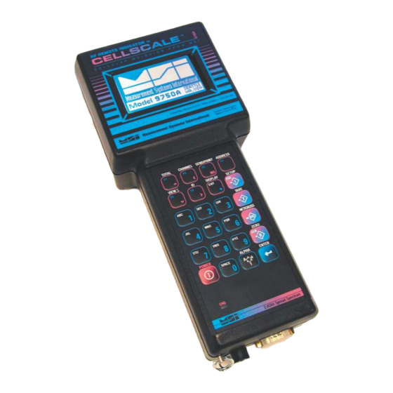
- Page 1 MSI9750A RF Remote Weight Indicator CellScale System ® a component of the User Guide Measurement Systems International...
- Page 2 9750A HANDHELD RF REMOTE INDICATOR for CALE ® Page 2 MSI-9750A RF Remote Indicator • User Guide...
-
Page 3: Table Of Contents
MEASUREMENT SYSTEMS INTERNATIONAL TABLE OF CONTENTS 1– I & O .... 4 7 – 9750A M ......35 ECTION NTRODUCTION RIENTATION ECTION ETER ETUP 9750A Keyboard ..........4 System Setup Menu ........35 Key Descriptions ..........5 Set Time & Date ..........35 9750A Display Symbols ........ -
Page 4: Section 1- Introduction & Orientation
CALE SECTION 1 – INTRODUCTION & ORIENTATION INTRODUCTION The Measurement Systems International MSI-9750A RF Remote Indicator is an accessory component of MSI's ® CellScale System. Combined with 1 or more CellScales, the 9750A provides complete control over all scale and ®... -
Page 5: Key Descriptions
MEASUREMENT SYSTEMS INTERNATIONAL KEY DESCRIPTIONS key turns the 9750A On and Off. The key must be held for 1 second to ensure startup. POWER POWER key is used to zero out residual weight on the scale. When entering numbers or strings the key is used ZERO ZERO... -
Page 6: 9750A Display Symbols
9750A HANDHELD RF REMOTE INDICATOR for CALE 9750A DISPLAY SYMBOLS The 9750A uses a full dot matrix graphics display which allows 3 sizes of fonts and full use of graphic symbols. On standard single channel and multi-channel displays, certain symbols are used for scale specific indications. ®... -
Page 7: General Information
MEASUREMENT SYSTEMS INTERNATIONAL GENERAL INFORMATION The 9750A is a versatile indicator capable of displaying many data items. As a member of the CellScale family the 9750A does not stand alone. It is a slave device to a MSI-9000 CellScale. All data displayed on the 9750A is received via RF from a master CellScale. -
Page 8: Features
9750A HANDHELD RF REMOTE INDICATOR for CALE FEATURES • Designed to meet or exceed all US and international standards. • Multiple Customized Display Modes, single channel or multiple channel modes ® • Reliable 2.4 GHz Frequency Hopping RF communications. Highly immune to interference and multi-path problems. -
Page 9: The Cellscale Family
MEASUREMENT SYSTEMS INTERNATIONAL THE CELLSCALE FAMILY 1) Model 9000 CellScale – Rugged unit for interfacing any scale and converting it to RF networking. 2) Model 9008 Multiplexer – Allows up to eight scales with independent calibrations, to share a single CellScale input channel. -
Page 10: Unit Installation
9750A HANDHELD RF REMOTE INDICATOR for CALE UNIT SETUP The 9750A is simple to setup and use. If there are no peripheral devices such as a printer or bar code scanner, setup consists of charging the battery, and setting the modem controls to talk to a 9000 CellScale. ®... -
Page 11: Rf Scale
MEASUREMENT SYSTEMS INTERNATIONAL SECTION 2 – RF SCALE COMMUNICATIONS – THE CELLSCALE SYSTEM The 9750A is a component of the MSI CellScale System. The CellScale system uses frequency hopping spread-spectrum RF Modem technology transmitting in the 2.4 GHz ISM band. RF Modems have been problematic as the RF bands are very hostile, corrupted by noise, path loss and inter- fering transmission from other radios. -
Page 12: Rf Network Setup
9750A HANDHELD RF REMOTE INDICATOR for CALE RF NETWORK SETUP The 9750A is a RF Modem connected device. The RF Modem requires setup to connect to one or more CellScales. The 9750A stores information for all 32 possible networks. Each network setting can be modified with the “Modem Settings Menu”. - Page 13 MEASUREMENT SYSTEMS INTERNATIONAL CONFIGURING FOR MULTIPLE NETWORKS The 9750A can access multiple CellScales by switching Networks. A press of the key will change the ADDRESS network allowing the 9750A to monitor and control different scales. Because each CellScale has both a network and a CS address, these must be set up with the “SETUP RF NETWORK”...
-
Page 14: Troubleshooting Rf Connection Problems
9750A HANDHELD RF REMOTE INDICATOR for CALE TROUBLESHOOTING RF CONNECTION PROBLEMS Most connection problems are caused by improperly set up RF Networks. Both the 9750A and the master CellScale unit must have identical Network numbers. In addition, the CS Address must match on both units. If the Net- work and/or CS Address of the CellScale is in question, you might have to connect a terminal to the CellScale to ®... -
Page 15: Rf Site Testing
MEASUREMENT SYSTEMS INTERNATIONAL RF SITE TESTING The 9750A provides a means to check the efficiency of RF transmissions using the RF Site Testing function. Program a function key (use the procedure in Section 4) to “RF Site Testing” to run the test. 1) Place the 9750A in close proximity of the master CellScale unit. -
Page 16: Section 3 - Scale Operation
9750A HANDHELD RF REMOTE INDICATOR for CALE SECTION 3 – SCALE OPERATION POWER To Turn On the Power ® 1) Press and hold for 1 second. The system Shows the MSI Logo followed POWER by a graphic of a Model 9000 CellScale. 2) The LCD then displays “MSI-9750A”, the Network currently loaded as the active If the system fails to con- Address, and the software version number. -
Page 17: Select The Display Channel
MEASUREMENT SYSTEMS INTERNATIONAL TO SELECT THE DISPLAY CHANNEL As mentioned above, the 9750A will access any channels setup in the CellScale. It does this with the “CHAN- NEL” function. Use the key to step from channel to channel as dictated by the Scan list stored in the CHANNEL CellScale. -
Page 18: Multi-Channel Page Display
9750A HANDHELD RF REMOTE INDICATOR for CALE To Switch Between Multi-Channel Display and Single Channel Displays 1) Highlight the channel you wish to see in the single channel mode by pressing the UP (^) or DOWN (v) cursor keys. 2) Once highlighted press DISPLAY. The highlighted channel will appear in the single channel mode. ®... -
Page 19: Tare
MEASUREMENT SYSTEMS INTERNATIONAL the scale will zero. The scale will accept a zero setting over the full Range of the scale (NTEP and other Legal-for-trade models may have a limited zero range). Zero settings above 4% of full scale will subtract from the overall capacity of the scale. For example if you zero out 100 lb. -
Page 20: Setup Tare Mode
9750A HANDHELD RF REMOTE INDICATOR for CALE Multiple Tare Memories The 9750A is capable of storing Tare values through the use of the ID Codes. Each ID code stores an independent Tare. See Section 3 “ID Codes” for more information. ®... -
Page 21: Units
MEASUREMENT SYSTEMS INTERNATIONAL UNITS Allows easy weight units conversions. Up to 8 Units are available. See “SETUP UNITS” in the CellScale Manual for details on activating the available units. Since Units are stored with each ID Code, the menu item for changing units is found in the “Product ID Codes”... -
Page 22: Section 4 - Function Keys
9750A HANDHELD RF REMOTE INDICATOR for CALE SECTION 4 – FUNCTION KEYS SETUP FUNCTION KEYS The 9750A has six FUNCTION keys that can be programmed to any of several functions. The default func- tions are: TOTAL, CHANNEL, SEND/PRINT, ADDRESS, VIEW TOTAL, and ID. These default functions are ®... -
Page 23: Function Key Descriptions
MEASUREMENT SYSTEMS INTERNATIONAL Default Function Keys ....Default for F1. Add the current weight to the total, or Auto Total On/Off. Add to Total ......Default for F2. When pressed, changes to the next channel in the Scan Index. Switch Channel between selected scale channels. If preceded by a number (1-32), the display will show the chosen channel position from the Channel scan list. -
Page 24: View Function Keys
9750A HANDHELD RF REMOTE INDICATOR for CALE it’s Host4 print string..Tells the CellScale to output it’s Host5 print string. Send to CS Host 5 ..Outputs Comm 1 print string to the DE-9 connector, and tells the CellScale to output Print &... -
Page 25: Custom Function Key Labels
MEASUREMENT SYSTEMS INTERNATIONAL Custom Function Key Labels The “Enter ID String 1” and “Enter ID String 2” function keys provide the user some additional capabilities. When designating a key for these text entry modes, the 9750A brings up a text entry screen that allows you to give a custom 8 character label for the ID String. -
Page 26: Id Codes
9750A HANDHELD RF REMOTE INDICATOR for CALE SECTION 5 – ID CODES • The CellScale can store 32 ID codes. The 9750A controls which ID Code is in use. • Each ID Code stores a Tare Value, a Total Value, a weighment counter, display mode (Net, Gross, Peak, etc...), ®... -
Page 27: Setup Id Codes Menu
MEASUREMENT SYSTEMS INTERNATIONAL SETUP ID CODES MENU Allows setup of ID Codes. A new ID can be created, the 8 character ID Name can be edited, two 20 character print strings can be assigned to each ID Code. Also any or all IDs can be deleted from this menu. �����������������... -
Page 28: Using Id Codes
9750A HANDHELD RF REMOTE INDICATOR for CALE USING ID CODES To Create a New ID Code (Short method) This procedure assumes the default for ENTER F6 has not been modified by the user. ® 1) Press ENTER, then (F6). 2) Using the numeric keypad enter a name for the new ID Code. Use the key to select letters as ALPHA required. -
Page 29: Id Code String 1 & 2
MEASUREMENT SYSTEMS INTERNATIONAL The following procedure deletes all existing ID Codes and any totals and statistics stored in them. To Delete all ID Codes This procedure will delete all the product ID codes and all associated Names, Strings, Totals and Statistics for the current active channel. To delete all product IDs for all channels, you must select a channel using the CHANNEL key, then repeat this procedure for each Channel. -
Page 30: Section 6 - Total / Statistics
9750A HANDHELD RF REMOTE INDICATOR for CALE SECTION 6 – TOTAL / STATISTICS TOTAL • The 9750A can add independent weighments together and keep a counter of how many weighments were ® added (Totaled). The Weighments counter can be thought of as a box or palette counter. •... -
Page 31: Setup Total Menu
MEASUREMENT SYSTEMS INTERNATIONAL Auto Total Operation 1) Enable the desired Auto Total mode in the “SETUP TOTAL” menu (see “SETUP TOTAL”). Select the “AUTONORM”, “AUTOLOAD”, or the “AUTOPEAK” mode. Exit from the setup menu. 2) Use the key to disable (“TTL OFF”) or enable (“TTL ON”) Auto Total. TOTAL 3) Place the weight to be totaled on the scale. -
Page 32: Turning Auto Total On & Off
9750A HANDHELD RF REMOTE INDICATOR for CALE To Set the Total Mode The following example assumes the F1 function key is in its default mode of “TOTAL”. 1) Press SETUP. 2) Press the switch (F1) or select Total. TOTAL ® 3) The current Total Mode is shown on selection 1. -
Page 33: Clearing Totals
MEASUREMENT SYSTEMS INTERNATIONAL To Clear the Total Value (Current ID Code only) At any time during the following procedure the EXIT key cancels the Clear operation. Clears ID’s statistics registers as well. 1) Press ∑. The current total is displayed. VIEW 2) Press CLR. -
Page 34: View Statistics And Grand Statistics
9750A HANDHELD RF REMOTE INDICATOR for CALE View Statistics and Grand Statistics The View Statistics feature uses totaled data from the current ID code in the CellScale to compute statistics. Grand Statistics uses totaled data from all ID codes. Only weight that has been totaled will be used in computing statistics. -
Page 35: Setup
MEASUREMENT SYSTEMS INTERNATIONAL SECTION 7 – 9750A SETUP SYSTEM SETUP MENU �������������������� ����������������� ��������������� �� � ��������������� �������������������� �� � ������������ �������������������� �� �� �������� �������������������� ���������������� �������������������� �� �� �� ���� � �� ��� �� ����� ��������� ������������� � �... -
Page 36: Password Locks
9750A HANDHELD RF REMOTE INDICATOR for CALE 3) Date Mode – Pressing changes the date mode from MM/DD/YY to DD-MM-YY. 4) Time Mode – Press to change between 24 hour time or 12 hour time with AM/PM indication. 5) Daylite (sic) Saving – Press to select the Daylight Saving mode. -
Page 37: Keyboard Lock
MEASUREMENT SYSTEMS INTERNATIONAL KEYBOARD LOCK Keyboard lock is provided to prevent casual or accidental pressing of the keys from changing any modes. This function works only from weight display modes. RESET ALL: The following procedure will cause you to lose all setups and will return the 9750A to it’s default settings. -
Page 38: Single Channel Preset Displays
9750A HANDHELD RF REMOTE INDICATOR for CALE IDC ..... The ID Code number in the form xxI. e.g. 2I is ID Code 2. IDName-- ... The ID Code name. The name must be programmed by either the CellScale or the 9750A. xS or xSL .... -
Page 39: Multi-Channel Preset Displays
MEASUREMENT SYSTEMS INTERNATIONAL Multi-Channel Preset Displays Multi-channel presets use the scan list position to assign channels to specific locations. After selecting the preset multi-channel display, the user can reassign any channel in the scan list to any screen location. The Multi-Channel Preset Displays are described by line numbers 1-8 corresponding to the small font layout. The numbers in the sample screens and descriptions correspond to the scan list position index (SLI). - Page 40 9750A HANDHELD RF REMOTE INDICATOR for CALE SCALE DISPLAY SETUP MENU – PRESET DISPLAYS SCALE DISPLAY SETUP BACKLIGHT 1 Off (max batt-life) Shortcut 2 On for 15 seconds 1 Single Scale Mode 2 Multi Scale Mode 3 On for 30 seconds ®...
-
Page 41: Using Display Setup
MEASUREMENT SYSTEMS INTERNATIONAL display modes are described on the previous page. 3 Backlight – Controls the duration of the backlight. The duration resets every time a key is pressed. Setting for shorter times increases battery life. USING DISPLAY SETUP The 9750A weight display is a primary means of getting and using CellScale data. The user should always select a single channel weight display mode that provides the information needed. -
Page 42: Custom Display Setup
9750A HANDHELD RF REMOTE INDICATOR for CALE CUSTOM DISPLAY SETUP The 9750A weight display is fully customizable. Both the single channel and multi-channel displays can be customized. All available data types plus custom text can be located anywhere on the screen in any of three font sizes: 1) Large Font –... - Page 43 MEASUREMENT SYSTEMS INTERNATIONAL Screen Formatting The 9750A LCD Screen allows a wide variety of scale display screen setups. The illustrations here demonstrate some of the possibilities. The custom display setup menus control the type and placement of available data types. The LCD is a graphics type organized in rows and columns.
- Page 44 9750A HANDHELD RF REMOTE INDICATOR for CALE Line Preview The bottom two lines of the Row Setup menu illustrate what the line has programmed into it. Data is displayed in row pairs. For example, while programming row 6, row 5 and 6 will be illustrated. When data from another line is present, as it will be with the large font, the preview area will show as lines.
-
Page 45: Custom Display Setup Procedure
MEASUREMENT SYSTEMS INTERNATIONAL Selecting Items for Display The custom display setup menus provide access to all the data the scale can provide. When an item is present on the display, it will have an arrow next to its selection number. The length of some data items are fixed, but many have variable lengths. -
Page 46: Single Channel Custom Display Menu
9750A HANDHELD RF REMOTE INDICATOR for CALE CUSTOM SINGLE CHANNEL DISPLAY SETUP MENU ������������������� �������������������� ������������ ������������������� ������������������� ® ������������������ �������������� ��������������������� ��������������� ����������� ������������ ���� ������������������ �������������� ��������������� ������������� ��������������� �������������������� ������������� ������������ ��������������� ����������������� ��������������������� ���������������� �������������������� �������������������� ������������������... -
Page 47: Multi-Channel Custom Display Menu
MEASUREMENT SYSTEMS INTERNATIONAL CUSTOM MULTI-CHANNEL DISPLAY SETUP MENU ������������������� �������������������� ������������ ������������������� ������������������� ������������������ �������������� ��������������������� ��������������� ����������� ������������ ���� ������������������ �������������� ��������������� ������������� ��������������� ������������������ ������������� �������������������� ��������������� ������������������ ��������������������� �������������������� �������������������� ����������������� ������������������ ���������������� ����������� ������������������� ��������������� �������������� ���������������... -
Page 48: Section 8 - Set Points
9750A HANDHELD RF REMOTE INDICATOR for CALE SECTION 8 – SET POINTS INTRODUCTION The CellScale system provides extensive Set Point capabilities. Up to 32 Set Points are available. The CellScale ® performs the A/D conversions and does limit checking for all the Set Points. The 9750A receives Set Point infor- mation from the CellScale and responds as programmed. -
Page 49: Set Point Setup Menu
MEASUREMENT SYSTEMS INTERNATIONAL SET POINT SETUP MENU There are three ways to program values, operators, and remote relays for Set Points. 1) Use the Terminal Interface Mode at the CellScale, 2) use a 3750CS, or 3) use the 9750A. To Enter the Set Point Setup Menus 1) Press SETUP. -
Page 50: To Activate/Inactivate All Set Points
9750A HANDHELD RF REMOTE INDICATOR for CALE PROGRAM SET POINT MENU �������������������� �������������������� �������������������� ® �������������������� �������������������� �������������������� �������������������� �������������������� �������������������� ����������� ������������������ ������������������� �������������������� This Set Point Menu is reached from the procedure on ������������������� the previous page. 1) Individual Set Points are turned on (enabled) or ���������������������... -
Page 51: Program Set Point Menu
MEASUREMENT SYSTEMS INTERNATIONAL 9750A RESPONSE MENU The 9750A responds to set points in three ways: with an audible alarm, a message display, or a message sent to comm port 1. These menus program this response. ������������ ��������������������� ��������������������� ��������������������� ��������������������� ��������������������... -
Page 52: Set Pont Formula Menu
9750A HANDHELD RF REMOTE INDICATOR for CALE SET POINT FORMULA MENU FORMULA 1 Operator 1 > 2 Value 1 XXXXXXX 3 Val 1 Type GROSS ® 4 Dual Value 5 Preact XXXXXXX 6 Deadzone XXXXXXX OPERATOR 1 7 View Formula 1 Greater Than >... -
Page 53: Section 9 - Communication Port
MEASUREMENT SYSTEMS INTERNATIONAL SECTION 9 – COMMUNICATION PORTS INTRODUCTION • The MSI 9750A is equipped with a single RS-232 serial input / output. The Comm Port is intended for inter- facing printers, data loggers, scoreboards, and computers to the 9750A Meter. The real-time clock allows the user to time and/or date stamp any data obtained from the 9750A. -
Page 54: Comm Port Setup Menu
9750A HANDHELD RF REMOTE INDICATOR for CALE the weight is in motion and/or not stable. 3) Print on CTS (Clear to Send, a RS-232 handshake line) – By toggling the CTS line from space to mark, the print string will be transmitted. If an interval is set, the string will continue to print as long as CTS is asserted. “Motion Check”... - Page 55 MEASUREMENT SYSTEMS INTERNATIONAL ����������������� ����������� ��������������� ����������������� ������������ �������������������� ��������������������� �������� ����������������� �������������������� ���������������� ������������������ ���������� ������������������ ����������������� ����������������� ������������������ ������� ��������������������� ������ �������������������� �������������� ��������������������� �������������� TRIGGER PRINT ON: The �������������������� ������������������� “Trigger Print On’ menu designates ����������������� ����������������� the condition that causes the 9750A �������������...
-
Page 56: General Text Entry
9750A HANDHELD RF REMOTE INDICATOR for CALE 5) MODE: The MODE menu sets the communications mode for the port. Use “TALK” for outputting data to a printer that uses hardware handshaking or no handshaking. Use “DUPLEX” for printers with software hand- shaking (XON / XOFF, etc.) or to talk and listen to a computer. - Page 57 MEASUREMENT SYSTEMS INTERNATIONAL GENERAL TEXT ENTRY MENU ���������������� ���������������� ������������� ������������������� ��������������� �������������������� �������������� �������������������� �������������������� ��������������� �������������������� �������������������� �������������� ����������� �������������������� ��������������� ���������������� ������������������ ��������������������� ������������������ ������������������� �������������� �������������������� ��������������� ������������������ �������������� ������������������ ��������������� �������������� �������������� ������������������ � ��� ������������...
-
Page 58: Printer Output Formatting
9750A HANDHELD RF REMOTE INDICATOR for CALE Alternate Characters, Punctuation, Symbols, and Control Characters 1) While in the text entry screen, press the key. This enables the ASCII Characters Menu. This menu [F4] provides links to special characters. 2) For standard punctuation, press [1]. For other printable characters, press [2]. For ASCII control characters, ®... -
Page 59: End Of Line / Start Of Line Strings
MEASUREMENT SYSTEMS INTERNATIONAL 6) @W3 causes the current Net weight to be printed. If the scale was in the NET mode, @W1 would have worked as well. 7) @D6 causes the current date to be printed in MM/DD/YYYY format 8) @E causes the end-of-line string to be sent (CR/LF). PROGRAMMING THE END OF LINE OR START OF LINE STRINGS The End of Line String is used to terminate print strings and is printer dependent. -
Page 60: Serial Output "@" Commands
9750A HANDHELD RF REMOTE INDICATOR for CALE SERIAL OUTPUT “@” COMMANDS The printer formatting “@” commands and their data configurations are as follows: Change to next SC Index (Channel List entry) ® Use the @+ command to change to the next entry in the SC Index. All subsequent commands which are chan- nel related will be directed to the new active Channel. - Page 61 MEASUREMENT SYSTEMS INTERNATIONAL Print date in the form DD/MM/YY (European Standard) Print the day of the week Full alpha date in the form DDMMMYYYY with month spelled out Print date in the form MM/DD/YYYY Print date in the form DD/MM/YYYY (European Standard) Print date in the form YYYYMMDD (ISO Standard) Output Data Form: 25JUL03...
- Page 62 9750A HANDHELD RF REMOTE INDICATOR for CALE “x” tabs are printed (limited to 99). For more tabs use two @H commands in series. OUTPUT RF MODEM ID Use the @I command to print the RF Modem ID numbers of the connected CellScale and the internal 9750A ®...
- Page 63 MEASUREMENT SYSTEMS INTERNATIONAL Output Data Form: ****** Length: 8 or 9 with DP. Justification: left GROSS Length: 6 Justification: left Length: 6 Justification: left TARE Length: 6 Justification: left TOTAL Length: 6 Justification: left T-CNT Length: 6 Justification: left TOTAL, T-CNT Length: 12 Justification: left If Gross weight is added GROSS+...
- Page 64 9750A HANDHELD RF REMOTE INDICATOR for CALE Length: 4 Justification: left PRINT TIME ® Use the @T command to print the current time register from the real-time Clock. Input Data Form: 12 hour format with HH:MM 12 hour format with HH:MM:SS 24 hour format with HH:MM 24 hour format with HH:MM:SS Output Data Form:...
- Page 65 MEASUREMENT SYSTEMS INTERNATIONAL PRINT WEIGHT FULLY Use the @W command to print the current weight with units and mode printed. Input Data Form: Displayed weight with units and mode Gross weight Net weight Note: will print dashes if NET mode is not enabled Tare weight Note: will print zeros if no Tare value has been established Total weight...
- Page 66 9750A HANDHELD RF REMOTE INDICATOR for CALE 1234567.05 Length: 10 Justification: right, leading zeros suppressed 12345678 Length: 10 Justification: right, leading zeros suppressed ® PRINT STATISTICS FULLY Use the @Y command to print the statistics of the current ID Code with text descriptor. Input Data Form: Average weight Minimum weight...
- Page 67 MEASUREMENT SYSTEMS INTERNATIONAL PRINT CURRENT SC INDEX Use the @? command to cause the output to send the SC Index number of the active analog channel. Input Data Form: Print current scan index position number Print current scan index number (blank positions removed). If there are no blank positions in the scan list, then @?1 and @?2 will return the same number.
-
Page 68: Section 10 - Data Logging
9750A HANDHELD RF REMOTE INDICATOR for CALE SECTION 10 – DATA LOGGING INTRODUCTION The 9750A has two battery backed memory locations for storing scale data. Predefined function keys are available ® for storing user configured data directly to either memory location. Data Logging uses the “Data Out String” and “Aux String”... -
Page 69: Auto Print To Memory
MEASUREMENT SYSTEMS INTERNATIONAL DATA LOGGING CONTROL MENU The Data Logging Control Menu provides a means to upload stored data, and erase the data logging memory locations. The Data Logging Control Menu ������������ �������������������� is reached by pressing ����������������� SETUP ����������������� �����... -
Page 70: Section 11 - Text Messaging
9750A HANDHELD RF REMOTE INDICATOR for CALE SECTION 11 – TEXT MESSAGING The MSI-9750A provides a means for sending messages from host computers directly to the 9750A display. The remote computer uses a host command to send data to any 9750A on the same network (0-31). Once the 9750A receives a text message, it is displayed until a key is pressed. -
Page 71: 9750A To Host Message
MEASUREMENT SYSTEMS INTERNATIONAL 9750A TO HOST MESSAGES Once a sent message is observed by the 9750A user, pushing any key will clear the message and return the 9750A to the last display mode. An acknowledgment string is automatically sent back to the modem that generated the message. -
Page 72: Section 12 - Bar Code Functions
9750A HANDHELD RF REMOTE INDICATOR for CALE SECTION 12 – BAR CODE The Bar Code features of the 9750A allow the user to add scanned data to weight readings and trigger transmis- sions directly into RF connected computers. In combination with the Data Logging features, bar code scans can trigger data storage for uploading later. - Page 73 MEASUREMENT SYSTEMS INTERNATIONAL ����������������� ������������������ ��������������� �������������������� ������������ �������������������� �������� �������������������� ���������������� �������������������� ��������� �������������������� ������� �������������������� �������������������� ������������������ �������������������� To set up the Bar Code reader, press then [5]. SETUP ����������������� 1) BarCode 1 – Designates the output mode when data ����������������...
-
Page 74: Bration
9750A HANDHELD RF REMOTE INDICATOR for CALE SECTION 13 – CHANNEL SETUP & CALIBRATION ��������������������� �������������������� CHANNEL SETUP MENU ���������������� ������������������� �������������������� ® ��������������������� ��������������������� �������������������� �������������� ������������������� ��������������������� � ��� �������� ������ �������������� ������������ ��������� The Channel Setup Menu provides control of Channel settings in ��������������������... -
Page 75: Calibrate General Information
MEASUREMENT SYSTEMS INTERNATIONAL CALIBRATE GENERAL INFORMATION The following sections are intended for qualified scale technicians. The CellScale can be calibrated either directly using the Terminal Interface mode, or by using a 9750A or 3750CS. See the CellScale operators guide for informa- tion on direct calibration. -
Page 76: Enable/Disable Azm
9750A HANDHELD RF REMOTE INDICATOR for CALE ENTER to ��������������������� ���������������� Recalibrate ������������������� ��������������������� CLR to Reset Cal ��������������������� ® �������������������� ESC to Exit Cal ������������������� �������������������� RESETING CALIBRATION ��������������������� CALIBRATION LOCK ����������������� �������� PRESS SEALSWITCH ����������� ����������������� ON CELLSCALE TO �������������... -
Page 77: Motion Band
MEASUREMENT SYSTEMS INTERNATIONAL TO ENABLE / DISABLE AZM (AUTO ZERO MAINTENANCE) AZM is used to adjust out variations at zero caused by debris or water on the scale, temperature drift, and any other minor variation that affects the zero setting. Typically AZM is set to 0.5d or 1d, which is adequate for most modern scale systems. -
Page 78: Center Of Zero Indicator
9750A HANDHELD RF REMOTE INDICATOR for CALE CENTER-OF-ZERO (COZ) INDICATOR The COZ indicator turns on when the scale is within 1/4 d of the last zero setting. Some legal-for-trade jurisdic- tions require its use. To Enable/Disable the COZ Indicator ® Before starting the following procedure, you must be in the Top Menu Level of Calibration. -
Page 79: Reset All
MEASUREMENT SYSTEMS INTERNATIONAL CELLSCALE SIDE ORIENTATION Antenna Side Front Side Left Right Side Side Connector RESET ALL Backside Edge This procedure returns all registers of the 9750A to defaults. DO NOT initiate this function unless you are pre- pared and qualified to perform a complete setup of the 9750A system. This operation does not clear calibrations or affect any connected CellScales. - Page 80 9750A HANDHELD RF REMOTE INDICATOR for CALE MSI Boot Loader Version 3.K3 Update Application ® Change Baud Rate (ESC) Start Application Enter Command : 8) Choosing a faster baud rate will decrease the amount of time required to complete the update. However, baud rates above 38400 usually require a 5 wire serial cable (include RTS and CTS) and a terminal program that supports hardware handshaking.
- Page 81 MEASUREMENT SYSTEMS INTERNATIONAL xxxx Send (Upload) the file During Bootloading, the 9750A will display this screen When the upload is complete the following will appear in the PC Terminal window. CBFF Send (Upload) the file : Upload complete Erasing sector 1 of 7 Erasing sector 2 of 7 Erasing sector 3 of 7 Erasing sector 4 of 7...
-
Page 82: Appendixa - Menu Maps
9750A HANDHELD RF REMOTE INDICATOR for CALE APPENDIX A – MENU MAPS SETUP SELECT MENU ����������������� ����������������� ® ��������������� ��������������������� ������������ �������������������� �������� ���������� ���������������� ������������������ ��������� ������������������ ������� ������ ��������������������� ��������������������� PASSWORD LOCKS ����������������� �������������� ��������������� ������������ ����������������� �������� ���������������������... - Page 83 MEASUREMENT SYSTEMS INTERNATIONAL FUNCTION KEYS ��������������� �������������������� ������������������ ������������ �������������������� �������������������� �������� ������������������ �������������������� ���������������� �������������������� �������������������� ����������������� ������������������ �������������������� ������� �������������������� ������������������� �������������������� �������������������� �������������������� �������������������� �������������������� �������������������� ��������������������� �������������������� ������������������� ������������������� �������������������� �������������������� ���������������� ���������������� ��������������������� �������������������� ���������� �������������������...
- Page 84 9750A HANDHELD RF REMOTE INDICATOR for CALE SERIAL & STRINGS ����������������� ����������� ��������������� ® ����������������� ������������ �������������������� ��������������������� �������� ����������������� �������������������� ���������������� ������������������ ���������� ������������������ ����������������� ����������������� ������������������ ������� ��������������������� ������ �������������������� �������������� ��������������������� �������������� �������������������� ������������������� ����������������� ����������������� ������������� ������������������...
- Page 85 MEASUREMENT SYSTEMS INTERNATIONAL PRODUCT ID CODES ����������������� ����������������� ��������������������� ��������������� ��������������������� ��������������������� ������������ �������������������� ���������������� �������� ���������� ��������������������� ���������������� ������������������ ����������������� ��������� ������������������ �������������� ������� ������ ��������������������� ��������������������� ��������������������� ���������������� �������������������� �������������������� ����������� ��������������� BAR CODE SETUP ��������������������� ����������������� ������������������ ���������������������...
- Page 86 9750A HANDHELD RF REMOTE INDICATOR for CALE TARE SETTINGS ������������� ��������������������� � ������������������ �������������������� ® �������������������� � ������������������ �������������������� RF MODEM SETTINGS �������������� ��������������� ��������������������� ������������������� ��������������������� ����������������� ��������������������� ������������������ ��������������������� ���� 17 ��������������������� ��������������������� ��������������������� ������������������� �������������������� ����������������� ������������������� �����������������...
- Page 87 MEASUREMENT SYSTEMS INTERNATIONAL SCALE DISPLAY SETUP SCALE DISPLAY SETUP BACKLIGHT 1 Off (max batt-life) Shortcut 1 Single Scale Mode 2 On for 15 seconds 2 Multi Scale Mode 3 On for 30 seconds 3 Backlight 2min 4 On for 1 minute 5 On for 2 minutes 4 Backlight Level 5 Contrast...
- Page 88 9750A HANDHELD RF REMOTE INDICATOR for CALE SCALE SINGLE CHANNEL CUSTOM DISPLAY SETUP ������������������� �������������������� ������������ ������������������� ������������������� ® ������������������ �������������� ��������������������� ��������������� ����������� ������������ ���� ������������������ �������������� ��������������� ������������� ��������������� �������������������� ������������� ������������ ��������������� ����������������� ��������������������� ���������������� �������������������� �������������������� ������������������...
- Page 89 MEASUREMENT SYSTEMS INTERNATIONAL SCALE MULTI-CHANNEL CUSTOM DISPLAY SETUP ������������������� �������������������� ������������ ������������������� ������������������� ������������������ �������������� ��������������������� ��������������� ����������� ������������ ���� ������������������ �������������� ��������������� ������������� ��������������� ������������������ �������������������� ������������� ��������������� ������������������ ��������������������� �������������������� �������������������� ����������������� ������������������ ���������������� ����������� ������������������� ��������������� �������������� ���������������...
- Page 90 9750A HANDHELD RF REMOTE INDICATOR for CALE CHANNEL / CALIBRATE SETTINGS ��������������������� �������������������� ���������������� ������������������� �������������������� ��������������������� ��������������������� ® �������������������� �������������� ������������������� ��������������������� � ��� �������� ������ �������������� ������������ ��������� �������������������� �������� �������������������� �������������������� �������������������� �������������������� �������������������� �������������������� ���������������������� ��������� ���������������������...
- Page 91 MEASUREMENT SYSTEMS INTERNATIONAL SYSTEM SETTINGS �������������������� ����������������� ��������������� �� � ��������������� �������������������� �� � ������������ �������������������� �� �� �������� �������������������� �� �� �� ���� ���������������� �������������������� � �� ��� �� ����� ��������� ������������� � � �� ��� �� ����� ������� ��������������������...
- Page 92 9750A HANDHELD RF REMOTE INDICATOR for CALE CALIBRATION ENTER to ��������������������� ���������������� Recalibrate ������������������� ��������������������� CLR to Reset Cal ��������������������� ® �������������������� ESC to Exit Cal ������������������� �������������������� RESETING CALIBRATION ��������������������� CALIBRATION LOCK ����������������� �������� PRESS SEALSWITCH ����������� ����������������� ON CELLSCALE TO �������������...
- Page 93 MEASUREMENT SYSTEMS INTERNATIONAL GENERAL TEXT ENTRY ���������������� ���������������� ������������� ������������������� ��������������� �������������������� �������������� �������������������� �������������������� ��������������� �������������������� �������������������� �������������� ����������� �������������������� ��������������� ���������������� ������������������ ��������������������� ������������������ ������������������� �������������� �������������������� ��������������� ������������������ �������������� ������������������ ��������������� �������������� �������������� ������������������ � ��� ������������ ���������������������...
- Page 94 9750A HANDHELD RF REMOTE INDICATOR for CALE SET POINTS ® ����������������� ����������������� �������������������� �������������������� ������������������� �������������������� ������������� ������� �������������������� ��� 1 ������������� �������������������� �������������������� �������������������� ��������������� ������������������ �������������������� �������������������� ������������������ �������������������� �������������������� �������������������� �������������������� �������������������� �������������������� �������������������� ������������������� �������������������� �������������������� �������������������...
-
Page 95: Ppendixb - Ascii Chart
MEASUREMENT SYSTEMS INTERNATIONAL APPENDIX B – ASCII CHART Firmware Version 2-XX ® MSI CellScale System • 9750A User Guide Page 95... -
Page 96: Features
9750A HANDHELD RF REMOTE INDICATOR for CALE APPENDIX C – SPECIFICATIONS & SUMMARY OF FEATURES Temperature Range Display ® • 64 x 128 Full Graphics Module • -20° C to +60° C Operating (-4° F to 140° F) • Multiple Font sizes, up to 8 lines of 20 characters •... -
Page 97: The Msi Limited Warranty
THE MSI LIMITED WARRANTY MEASUREMENT SYSTEMS INTERNATIONAL, INC., WARRANTS load sensing elements and meters against defects in workmanship and materials for a period of one year from date of purchase and warrants electrical cables and batteries against the same defects for a period of ninety (90) days from date of purchase.
Need help?
Do you have a question about the MSI9750A and is the answer not in the manual?
Questions and answers