
Summary of Contents for Celec LTR7000
- Page 1 User’s & Technical Manual – LEVEL TRANSMITTER LTR7000 LEVEL TRANSMITTER LTR7000 INDUSTRIAL ELECTRONICS GELEC Industrial Electronics PAGE 1...
-
Page 2: Table Of Contents
User’s & Technical Manual – LEVEL TRANSMITTER LTR7000 CONTENTS PRECAUTIONS! ..............................3 MANUFACTURER WARRANTY, GENERAL TERMS AND CONDITIONS ........... 4 DISPOSAL OF OLD ELECTRICAL & ELECTRONIC EQUIPMENT ..............5 LEVEL TRANSMITTER LTR7000 ........................5 GENERAL DESCRIPTION ..........................6 FEATURES ................................. 8 LTR7000 OVERVIEW &... -
Page 3: Precautions
User’s & Technical Manual – LEVEL TRANSMITTER LTR7000 PRECAUTIONS! There are no serviceable parts inside the LTR7000 unit. Not to be opened by any unauthorized person. Any repair, modification, or configuration of the device must be carried out by the manufacturer, or a qualified service engineer familiar with the application. -
Page 4: Manufacturer Warranty, General Terms And Conditions
All products are designed and produced by the manufacturer GELEC Co. LP to be in compliance with the EU norms applying to them. GELEC is not responsible for direct or indirect damages or malfunction caused by improper use or installation of the LTR7000. GELEC Industrial Electronics... -
Page 5: Disposal Of Old Electrical & Electronic Equipment
In order to ensure the best performance and effective use of the LTR7000, we recommend that you read the information in this manual carefully and follow the instructions contained. -
Page 6: General Description
With 7mm sensing resolution and a variety of standard analog signals that can be assigned by the user to any level range up to 205cm, the LTR7000 is an ideal solution for industrial, heavy-duty level measurement applications. - Page 7 User’s & Technical Manual – LEVEL TRANSMITTER LTR7000 MAIN FEATURES High measuring accuracy (7mm resolution) in industrial environment Five length versions available (65/100/135/170/205 cm) Two analog outputs (mA/V) Five signal standards available (4-20, 0-20, 4-21mA / 0-5, 0-10V) ...
-
Page 8: Features
FEATURES LTR7000 VERSIONS LTR7000 is provided in five length versions, depending on the maximum level height that the device can measure. The resolution is the same in all versions, while the different length options cover a wide range of installation configurations. - Page 9 TWO ERROR STATES - ERROR OUTPUT LTR7000 is designed to detect and manage two Error states that are likely to occur. As long as the device is in Error state, the STATUS LED indicates the problem and a...
- Page 10 #3 and #4 with a cable. Turn on the power for a few seconds, the problem should be solved and the LTR7000 should not be in Error state. Check the external circuit for disconnections.
-
Page 11: Ltr7000 Overview & Configuration
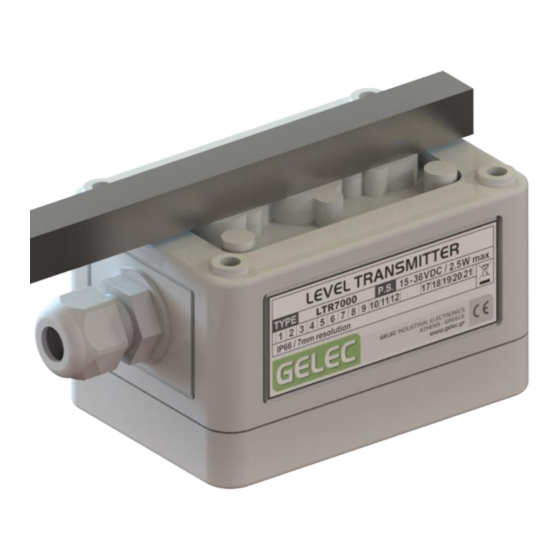
User’s & Technical Manual – LEVEL TRANSMITTER LTR7000 LTR7000 OVERVIEW & CONFIGURATION The LTR7000 is a level transmitter with a 6-pole terminal block, a calibration button, a configuration dip-switch and a status LED. Its consists of a 12x12 mm AISI 304 stainless steel square tube and an IP66 fiber-glass reinforced polycarbonate housing with all-round foamed-in PU seal, proper for electronic devices exposed in harsh industrial environment. - Page 12 User’s & Technical Manual – LEVEL TRANSMITTER LTR7000 SW1/SW2 switches (mA output range selection) With SW1/SW2 switches you can select the mA output range at terminals #3 / #4 (COM) 4 - 20 mA → SW1 : OFF , SW2 : OFF...
- Page 13 The STATUS LED inside the transmitter enclosure, indicates various operational stages of the LTR7000. This LED is useful during connection and calibration stages and it is not visible during normal operation with the cover screwed on the enclosure. Consult the following table for quick reference and the relevant sections for detailed information.
-
Page 14: Installation
If the enclosure becomes damaged, disconnect the device immediately and order a replacement. The two engraved lines on the LTR7000 (measuring segment) and the float’s magnet can be seen in the pictures above highlighted in red, along with the proper installation of a fully operating system. - Page 15 Since there is no direct contact between any part of the LTR7000 and the measured fluid, the system supports both atmospheric and high-pressure applications. The measuring chamber’s material must be non-magnetic.
- Page 16 User’s & Technical Manual – LEVEL TRANSMITTER LTR7000 PLACEMENT ON THE MEASURING CHAMBER The LTR7000 tube contains the hall effect sensor chain and has to be tangent to the measuring chamber, in order to be as close as possible to the magnetic float. On the back of the tube, at the side that faces the measuring chamber, there are two engraved lines that define the active measuring segment (check the relevant section for more details).
-
Page 17: Electrical Section
User’s & Technical Manual – LEVEL TRANSMITTER LTR7000 ELECTRICAL SECTION ELECTRICAL CONNECTIONS The LTR7000 is equipped with a 6-pole terminal block. The terminal block is manufactured to provide resistance to stress, corrosion, cracking, electrolytic corrosion and screw loosening in case of vibrations. This way, conductor connections are maintained reliable and maintenance-free in harsh industrial environment. - Page 18 CONNECTION TERMINALS Read carefully the following information and refer to the connection diagrams and technical data, regarding proper wiring of the LTR7000 with the associated equipment. Confirm that you have proper connections before unit operation. Wrong connections may lead to permanent device or external equipment damage. Don’t proceed to any connection modification, while the unit is powered.
- Page 19 User’s & Technical Manual – LEVEL TRANSMITTER LTR7000 TERMINALS #3 - #4 (mA OUTPUT SIGNAL) Terminals #3 (I ) and #4 (COM) provide the mA output signal during operation. The output range (4-20mA / 0-20mA / 4-21mA) can be selected from the internal configuration dip-switch.
- Page 20 User’s & Technical Manual – LEVEL TRANSMITTER LTR7000 LTR7000 Connection Diagram (only mA output used) LTR7000 Connection Diagram (only V output used) GELEC Industrial Electronics PAGE 20...
- Page 21 User’s & Technical Manual – LEVEL TRANSMITTER LTR7000 LTR7000 Connection Diagram (V & mA outputs used) GELEC Industrial Electronics PAGE 21...
-
Page 22: Calibration Process - Default Settings
Notice that if the level during process exits the calibrated level limits, but it is still within the LTR7000 active measuring segment, there will not be an ERROR 2 output signal. In this case, the output maintains the minimum/maximum value of the selected output range. - Page 23 User’s & Technical Manual – LEVEL TRANSMITTER LTR7000 HIGH LEVEL ‘High Level’ is defined as the level where the LTR7000 provides the maximum output value of the selected output range (for example 20mA, if the selected range is 4-20mA). Unless otherwise stated on the product label, LTR7000 is factory calibrated to provide the maximum output when the float’s magnet (north pole) is aligned with the top...
- Page 24 User’s & Technical Manual – LEVEL TRANSMITTER LTR7000 OPERATING LEVEL (between LOW and HIGH) Any modification of the calibration must be processed by an engineer familiar with the device operation, the associated equipment and the application in general. GELEC Industrial Electronics...
- Page 25 User’s & Technical Manual – LEVEL TRANSMITTER LTR7000 IMPORTANT CALIBRATION NOTES In order to begin the calibration procedure, LTR7000 must be at its final installation position with all connections completed. Ensure that you have a proper electrical layout. Refer to the LTR7000 manual and ...
- Page 26 User’s & Technical Manual – LEVEL TRANSMITTER LTR7000 LOW-LEVEL CALIBRATION PROCEDURE LTR7000 should be in normal operation (STATUS LED constant GREEN) before proceeding. Set the fluid at the level you want the LTR7000 to provide the minimum output value and wait until it becomes calm.
-
Page 27: Dimensions
User’s & Technical Manual – LEVEL TRANSMITTER LTR7000 DIMENSIONS LTR7065 LTR7100 LTR7135 LTR7170 LTR7205 1140 1490 1840 2190 (TOTAL HEIGHT) 1000 1350 1700 2050 (MEASURING SEGMENT) (OFFSET) * All dimensions are in mm GELEC Industrial Electronics PAGE 27... -
Page 28: Technical Specifications
User’s & Technical Manual – LEVEL TRANSMITTER LTR7000 12. TECHNICAL SPECIFICATIONS LTR7000 GENERAL DATA Height 790 / 1140 / 1490 / 1840 / 2190 mm Width 65 mm Depth 68,5 mm Weight 600 / 790 / 980 / 1170 / 1360 gr... - Page 29 User’s & Technical Manual – LEVEL TRANSMITTER LTR7000 Electrical connection characteristics Terminal block configuration 6 poles / 3.5mm pitch Terminal block materials PA – UL 94 V0 Galvanized steel / Tin-plated cooper alloy Clamping parts resistance Electrolytic corrosion Rusting Stress corrosion cracking IEC rigid solid: 0,34 –...
- Page 30 User’s & Technical Manual – LEVEL TRANSMITTER LTR7000 INDUSTRIAL ELECTRONICS 4 Kikladon Str. Maroussi, Athens - Greece, GR-15125 Telephone: +30 210 6144074 - Fax: +30 210 6144074 - info@gelec.gr GELEC Industrial Electronics PAGE 30...