
Summary of Contents for Uniblitz N-CAS VINCENT ASSOCIATES VLM1
- Page 1 1.800.828.6972 User Manual VLM1/VLM1B Interface Module For the FS Shutter Series 14-0055 Version 1.01 2021...
- Page 2 For information regarding applicable intellectual property, please visit www.uniblitz.com/patents. For WARRANTY information please visit https://www.uniblitz.com/terms/ Information in this publication supersedes that in all previously published material. Due to our ongoing development program, Vincent Associates reserves the right to discontinue or change specifications or designs, at any time, without incurring any obligation.
-
Page 3: Table Of Contents
Table of Contents TABLE OF FIGURES ..................4 GENERAL SAFETY SUMMARY ..............5 Injury Precautions ...................... 5 Product Damage Precautions ..................5 Safety Terms and Symbols ..................6 PREFACE ......................6 GETTING STARTED ..................7 Features ........................ -
Page 4: Table Of Figures
NOTES ......................23 Table of Figures Figure 1: 5-Pin Pluggable Phoenix Connector ..................7 Figure 2: VLM1/VLM1B Rear Panel/View Layout ................9 Figure 3: VLM1/VLM1B Front Panel/View Layout ................10 Figure 4: VLM1/VLM1B SHUTTER Wire Installation Diagram ............. 12 ... -
Page 5: General Safety Summary
General Safety Summary Review the following safety precautions to avoid injury and prevent damage to this product or any products connected to it. To avoid potential hazards, use the product only as specified. Only qualified personnel should perform service procedures. Injury Precautions ... -
Page 6: Safety Terms And Symbols
Specifications are described for all input/output controls as well as operational features of the VLM1/VLM1B. What follows is the complete operator’s manual for the UNIBLITZ VLM1/VLM1B Interface Module. Please read this manual completely before operating the unit. Due to the construction of this unit, Vincent Associates recommends that the unit be returned to the manufacturer for repair. -
Page 7: Getting Started
Getting Started Features Two different models available – the VLM1, this unit is housed and comes equipped with a Power Supply, USB/Power Cable, and Accessories. The VLM1B is an open frame printed circuit card suitable for OEM applications, the only accessory included is a 2mm micro screwdriver (also included with the VLM1). -
Page 8: Introduction
The UNIBLITZ VLM1/VLM1B Interface Module is a convenient signal interface unit to control the UNIBLITZ FS shutter series from a +5V TTL control signal. The FS shutter requires only +5VDC to open and 0VDC to close – default position of the FS25/FS35 is closed. Although the interface circuit is quite simple, for those who do not wish to build their own interface, the VLM1/VLM1B available. -
Page 9: Operator Controls
Operator Controls VLM1/VLM1B Rear Panel Operator Connections VLM1 VLM1B Figure 2: VLM1/VLM1B Rear Panel/View Layout 1. PWR/COM: USB/Power Input - +5VDC 0.5A min (USB5, +5VDC 1A wall adapter included). A USB interface cable (USB A 2.0 to USB Micro B) is also included for use the USB5 power supply, or the cable can be connected to a computer to supply power and data. -
Page 10: Vlm1/Vlm1B Front Panel Operator Controls/Indicators
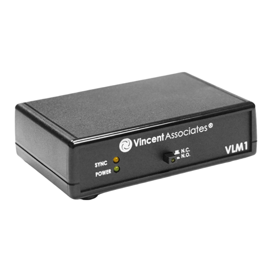
VLM1/VLM1B Front Panel Operator Controls/Indicators VLM1 VLM1B Figure 3: VLM1/VLM1B Front Panel/View Layout 5. POWER LED Power Indicator – GREEN LED Indicates the VLM1/VLM1B power status. 6. SYNC LED Sync Status Indicator – YELLOW LED Indicates the VLM1/VLM1B module’s electronic output status. -
Page 11: Start Up
Start Up Be sure to observe Electro-Static Discharge (ESD) anti-static unpacking procedures when removing the VLM1/VLM1B from the static shielding CAUTION bag. Improper handling can result in destruction of the CMOS integrated circuits. After unpacking your unit inspect for any defects. Upon inspection if a visible defect is found, or a part (or parts) are missing, notify Vincent Associates immediately. -
Page 12: Terminal Block Wire Installation
Terminal Block Wire Installation The following illustrates the Terminal Block Wire Installation procedure for the VLM1 or the VLM1B (not shown): 1. Be sure wire is stripped to length as shown. 2. Push desired wire terminal actuator in using 2mm screwdriver provided (as shown) 3. -
Page 13: Figure 5: Vlm1 To Fs Series Shutter - Interconnection Diagram
Figure 5: VLM1 to FS Series Shutter - Interconnection Diagram VLM1/VLM1B User Manual... -
Page 14: Operating Basics
This is referred to as Pulse Width Determined Exposure Time. The VLM1B can be easily integrated into OEM applications where a +5VDC power supply is available. Note that when a remote activate cable, the 710R (see https://www.uniblitz.com/products/710r- handheld-remote-cable/) or the 710R/F (see https://www.uniblitz.com/products/710rf-foot-activated- remote-cable/) can be plugged directly into the PULSE INPUT BNC only. -
Page 15: Bnc I/O Active State Selection
deactivates. The 710R or the 710R/f cannot be used when the Pulse Input BNC is reconfigured for Active High. Do not plug the remote cable into the SYNC Output CAUTION BNC, this could cause irreparable damage. BNC I/O Active State Selection To set the active state of the PULSE Input and SYNC Output, you must access the unit’s printed circuit board. -
Page 16: Figure 6: Vlm1 Dimensional Layout
Figure 6: VLM1 Dimensional Layout VLM1/VLM1B User Manual... -
Page 17: Figure 7: Vlm1B Dimensional Layout - Fuse/Jumper Locations
Figure 7: VLM1B Dimensional Layout - Fuse/Jumper Locations VLM1/VLM1B User Manual... -
Page 18: Usb Operation
In fact, in addition to the link above, the USB driver can be found on the same Flash Drive that this PDF User Manual is located – This user manual is also available for download at www.uniblitz.com. (*Each VLM1/VLM1 unit connected to a USB Hub will require a minimum of 0.5A each for operation.) -
Page 19: Specifications
Specifications System Characteristics Name Description VLM1/VLM1B Allows the FS Series Shutter to be operated from a TTL signal source Interface for user/computer control of an FS shutter Power Supply +5V 0.5A min (USB5 - 1A wall adapter included – VLM1 Only). A Requirements USB interface cable (USB A 2.0 to USB Micro B) is included (VLM1 only) for use with the USB5 Power Supply, or it can be... -
Page 20: External Output Characteristics
External Output Characteristics Name Description 74HCT04A Direct Output, ~4.5VDC at 4mA max - V SYNC OUTPUT BNC SYNC Output operational only with FS shutter equipped with Sync System Active High/Active Low output. On-board jumper selectable. Default - Active High. See BNC I/O Active State Selection. SHUTTER OUTPUT Pin #1 - Shutter actuator coil RED wire 5-Pin Pluggable Spring... - Page 21 General Characteristics (cont.) ‐20°C to 55°C (-4°F to 131°F) Storage Temperature VLM1 - 1.39 x 4.50 x 3.69 inches (35.3 x 114.3 x 93.5 mm) Size (HWD) VLM1B - 0.59 x 3.42 x 2.73 inches (15.0 x 86.9 x 69.3 mm) Weight VLM1 - 5.95 oz (0.169 kg) VLM1B - 2.28 oz (0.065 kg)
-
Page 22: Figure 8: Vlm1/Vlm1B Schematic Diagram
Figure 8: VLM1/VLM1B Schematic Diagram VLM1/VLM1B User Manual... -
Page 23: Notes
Notes VLM1/VLM1B User Manual...
Need help?
Do you have a question about the N-CAS VINCENT ASSOCIATES VLM1 and is the answer not in the manual?
Questions and answers