Table of Contents
Advertisement
Advertisement
Table of Contents

Related Manuals for Dynatron 900+

Summary of Contents for Dynatron 900+
- Page 2 DANGER - Explosion Hazard: Do not use in the presence of flammable gas or anesthetics. Do not use the Traction System near X-ray or Diathermy devices. These devices may emit high frequency noise that could affect the operation of the Dynatron ™ 900+ Traction device.
-
Page 3: Table Of Contents
+™ Dynatron 900 ABLE ONTENTS SECTION I ........................1 NTRODUCTION ........................1 BEFORE YOU TREAT A PATIENT ........................2 INSTALLATION AND FEATURES ..............................2 UNPACKING ..........................2 STANDARD COMPONENTS ..........................2 OPTIONAL ACCESSORIES SECTION II ......................3 PHYSICAL FEATURES ......................4... - Page 4 +™ Dynatron 900...
-
Page 5: Introduction
ECTION NTRODUCTION The Dynatron 900+ Traction system is intended for medical purposes for use in conjunction with traction accessories such as belts and harnesses to exert therapeutic pulling forces on the patient’s body primarily for the cervical and lumbar areas. -
Page 6: Installation And Features
110/120V 60 Hz AC (220V 60 Hz if applicable) outlet. The power cord must be firmly plugged into the Dynatron 900+ device. Do not place the cord or the device in a place where the cord could be tripped over or accidentally pulled out of its socket during a treatment. -
Page 7: Physical Features
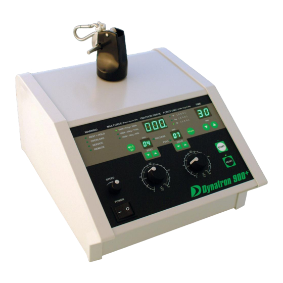
ECTION PHYSICAL FEATURES Before operating the Dynatron 900+, acquaint yourself with the physical and operational aspects of the device by reviewing the instructions and illustrations within this manual. The numbered features in the diagrams located at the end of this section correspond to the numbered descriptions on the following pages. -
Page 8: Description Of Physical Features
+™ Dynatron 900 DESCRIPTION OF PHYSICAL FEATURES OFF TOGGLE SWITCH The On/Off Toggle Switch is located on the left-side of the lower front panel. When the toggle switch is in the “1” (on) position, the LED above the Reset Key is illuminated green as well as other display windows and indicators on the device faceplate. - Page 9 +™ Dynatron 900 900+ YNATRON NUMBERED FEATURES...
- Page 10 +™ Dynatron 900 HOLD FORCE CONTROL KNOB Hold Force is set by using the circular knob located on the right-hand side of the device. There are three numbered circles surrounding the knob. The inside circle indicates force in Newtons, the middle circle indicates kilograms, while the outside circle indicates force in pounds.
- Page 11 POWER SOCKET Plug the Dynatron 900+ power cord firmly into the power socket located on the back of the device prior to plugging the device into a wall socket. Do not place the cord or the device in a place where the cord could be tripped over or accidentally pulled out of its socket during a treatment.
-
Page 12: Operating Instructions
ECTION OPERATING INSTRUCTIONS This section contains detailed procedures for the operation of the Dynatron 900+ Traction Unit. These procedures are designed to familiarize the user with the operation and function of the device. Read this section thoroughly along with all contraindications, warnings, and precautions before operating this device. -
Page 13: Detailed Treatment Setup
+™ Dynatron 900 DETAILED TREATMENT SETUP 1. According to manufactures’ instructions, prepare the patient for treatment. Make sure all belts and harnesses are securely attached. 2. The Remote Stop cable must be plugged into the console before the device is turned “on.”... - Page 14 +™ Dynatron 900 11. At the end of a treatment, the 900+ unit will beep (unless muted). The LED above the Rest key will flash, the Treatment Time Display Window will flash “00” and the tension on the rope will ramp down to 4 lbs.
-
Page 15: Additional Traction
1. Prepare the patient for the traction treatment. Make sure all belts and harnesses are securely attached. 2. Plug in the remote stop cable and hand it to the patient. 3. Turn on the Dynatron 900+ device. 4. Set Treatment Time: 1-99 min. -
Page 16: Special Usagep
2. Press the Start Key. The change will not take place until the next full Hold/Rest cycle. 3. In static mode, the Dynatron 900+ device will not accept any change until the Reset Key is pressed. -
Page 17: Contraindications , Decompression
Traction Therapy must be prescribed by a licensed practitioner following an appropriate physical examination and diagnostic analysis. The Dynatron 900+ Traction system is intended for medical purposes for use in conjunction with traction accessories such as belts and harnesses to exert therapeutic pulling forces on the patient’s body primarily for the cervical and lumbar areas. -
Page 18: Technical Information
SERVICE TO BE PERFORMED BY A TECHNICIAN ANNUAL CALIBRATION It is recommended that the Dynatron 900+ device be sent to the manufacturer for annual calibration. MAINTENANCE PERFORMED BY USER 1. Inspect the Dynatron 900+ ropes/cables and connectors daily for wear and damage. Replace accessories as needed. -
Page 19: Returning A Unit For Repair
CARE AND CLEANING INSTRUCTIONS • Clean the outer surface of the Dynatron 900+ device with a slightly damp or lightly moistened cloth. Mild household cleaners work well on the frame. Do not spray the solution directly on the unit. First moisten the cloth and then wipe the unit off. -
Page 20: Assembly And Maintenance
+™ Dynatron 900 ECTION ASSEMBLY AND MAINTENANCE PULLEY HEAD Whenever the Pulley Head is replaced or removed from the device, turn the pulley head to the left until the breach points are aligned and the pulley easily slips from the enclosure. Do not force. -
Page 21: Dynatron 900
+™ Dynatron 900 900+ YNATRON WALL INSTALLATION 1. Align 2 special mounting screws in screw holes (D). 2. Align with device with the mounting bracket. 3. Attach the device with hand-screws (E). 900+ YNATRON PLATFORM INSTALLATION 1. Align hole A on the machine with pin F on the installation plate. - Page 22 +™ Dynatron 900 MACHINED HOLE SIZES A. Alignment hole 3/8” dia. B. Alignment set pin holes ¼” dia. C. Screw-holes for table mou nt & wall mount 5/16”-18UNC D. Knob for wall bracket 5/16”-18UNC E. : Screw-holes for stand-mount or mounting bracket 5/16”-18UNC...
- Page 23 +™ Dynatron 900 HOW TO REPLACE THE TRACTION CABLE Traction cable should be non-conductive. Minimum cable strength 700 lbs. (320kgs/ 3200N). 1. Loosen the screw E. (Fig 1) 2. Pass the cable around pulley A. (Fig 1) 3. Thread the cable through the hole of pulley B, go around the main shaft and under cable;...
- Page 24 +™ Dynatron 900 HOW TO REPLACE FUSES Fuse 250V / 1.6A (100-120V) STEP Turning clockwise, use a screwdriver to reattach the fuse cover. STEP Turning counter clockwise, use a screwdriver to remove the fuse case cover. 250V / 0.8A (220-240V)
- Page 25 +™ Dynatron 900 DEFINITION OF SYMBOLS AND LABELING Some or all of the following symbols are included in the labeling for this device. Definitions accompany each symbol. Please read the Operations Manual Carefully before using this device. Electrical Safety – Class 1 / Type BF Manufacturer’s ID Label / 120V...
- Page 26 Guidance and Manufacturer's Declaration - Electromagnetic Emissions The Dynatron 900+ (and accessories) is intended for use in the electromagnetic environment specified below. The customer or the user of the Dynatron 900+ (and accessories) should assure that it is used in such an environment.
- Page 27 Guidance and Manufacturer's Declaration - Electromagnetic Immunity The Dynatron 900+ (and accessories) is intended for use in the electromagnetic environment specified below. The customer or the user of the Dynatron 900+ (and accessories) should assure that it is used in such an environment. Emissions Test...
- Page 28 Guidance and Manufacturer's Declaration - Electromagnetic Immunity The Dynatron 900+ (and accessories) is intended for use in the electromagnetic environment specified below. The customer or the user of the Dynatron 900+ (and accessories) should assure that it is used in such an environment. Immunity Test...
- Page 29 Dynatron 900+ (and accessories) The Dynatron 900+ (and accessories) is intended for use in an electromagnetic environment in which radiated RF disturbances are controlled. The customer or the user of the Dynatron 900+ (and accessories) can help prevent...
- Page 30 LIMITED WARRANTY Dynatronics CORPORATION warrants the Dynatron 900+, to be free from factory defects in materials and workmanship under normal use for ONE YEAR from the date of purchase by the original owner. If this product is defective within the...
- Page 31 +™ Dynatron 900...
- Page 32 I have received in-service training from my dealer and/or Dynatronics for this device. IMPORTANT: If there is anything about the operation or use of your Dynatron device that you do not understand, contact your dealer or Dynatronics for instruction. As a trained medical practitioner, you are solely responsible for determining appropriate application of this device for your patients.
Need help?
Do you have a question about the 900+ and is the answer not in the manual?
Questions and answers