
Summary of Contents for Telonics Handy Patch MC100
- Page 1 Telonics Pro Audio Handy Patch – MC100 Hand operated MIDI Controller User’s Manual Revision 3.2...
-
Page 2: Important Safety Instructions
IMPORTANT SAFETY INSTRUCTIONS CAUTION : Do not remove the rear cover. No user serviceable parts inside. Refer servicing to qualified service personnel. Read these instructions. Keep these instructions. Heed all warnings. Follow all instructions Do not use this apparatus near water. Clean only with a dry cloth. - Page 3 EMC CONFORMITY EMC / EMI This equipment has been assessed for radiated and conducted emissions compliance with reference to FCC Part 15 Class B and EN61000-6-3 standards and found to comply with the limits. This device complies with Part 15 of the FCC Rules. Operation is subject to the following two conditions: (1) This device may not cause harmful interference, and (2) This device must accept any interference received, including interference that may cause...
-
Page 4: Introduction
Before using the Handy Patch we would highly recommend you read the manual to gain an understanding of how the product functions. The Handy Patch was designed with Steel players, the Telonics TCA-500 Combo and the TC Electronic G-Major 2 Effects Processor in mind; however, it can be used as a MIDI controller for the Lexicon MX200 or any other MIDI controllable effects processor. -
Page 5: Table Of Contents
TABLE OF CONTENTS INTRODUCTION Important Safety Instructions............2 Introduction..................4 Table of Contents………………………………………………………………………… 5 Front Panel Controls & Connections Overview......6 NORMAL OPERATION Up / Down buttons…………………………………………………………………….. 7 Fast 1 & 2 buttons and Fast 3 footswitch………….………………………… 7 CC Wheel and Display………………………………………………………………… 8 Display Brightness button……………………………………………………………... -
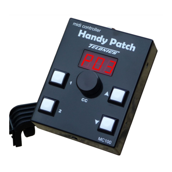
Page 6: Front Panel Controls & Connections Overview
Front Panel Controls & Connections Overview Handy Patch User’s Manual Rev 3.2... -
Page 7: Normal Operation
NORMAL OPERATION 1 – UP button When momentarily pushed the Preset number is increased by one; MIDI Program Change and Control Change messages are output to select the effect Preset number and set the effect volume level. If the Preset number is ‘P99’ when the button is pushed the display resets back to ‘P01’. -
Page 8: Cc Wheel And Display
6 – CC Wheel / button The CC Wheel (knob) has no rotational limits and also incorporates a push-button. The Control Change value can be read or stored by pushing the Wheel button and the value adjusted by rotating it. The 7-Display text below describes how the Wheel affects the display and the MIDI output. -
Page 9: Display Brightness Button
– See Fig 1. If the 7 Pin MIDI lead is used with the Telonics TCA-500B Combo power is picked up via the MIDI lead and no additional power supply is necessary – See Fig 2. -
Page 10: Mounting Adaptor
Note : Combo models TCA-500B onwards have a back panel connector that provides power to the Handy Patch. Earlier TCA-500 and TCA-500A Combo’s were not manufactured as standard with this connector fitted. This connector may be retrofitted to earlier models by the manufacturer. 11 –... -
Page 11: Basic Setup And Connections
Basic Setup & Connections Fig 1 - Handy Patch controlling an Effects Processor Standard MIDI Foot Switch Effects Processor Power to Handy Patch PS-2 Fig 2 - Handy Patch used with the TCA-500B Combo and FP-100 Volume Pedal MIDI Out + Power In (7 PIN) Foot Switch Power to Pedal TCA-500B... -
Page 12: Memorised Values
Fig 3 - TCA-500 Combo back panel connection The picture below shows the connections to the Combo using the Handy Patch 7 Pin MIDI lead. 12 – DC Power output socket 13 – MIDI In socket of the TC Electronic G-Major 2 Effects Processor. 14 –... -
Page 13: Setup Menu - Advanced Users
SETUP MODE – Advanced Users Accessing Setup Mode To enter Setup Mode – With no power applied - Press and hold the Fast 1 & 2 buttons – Apply power – The software version number should be displayed. Software Version Software released August 2015 - Version 1.10 Setup Menu Controls The UP or Down button is used to enter the Menu Selector... -
Page 14: Midi Channel Selection
n.01 – The Fast 1 button Preset number ……….. Setting range P01 to P99 ….. Default P10 n.02 – The Fast 2 button Preset number ……..… Setting range P01 to P99 ….. Default P25 n.03 – The Fast 3 footswitch Preset number …. Setting range P01 to P99 ….. Default P30 MIDI Channel selection The Handy Patch can be set to transmit on any MIDI Channel. -
Page 15: Cc Wheel & Control Change Controller Number Selection
CC Wheel & Control Change Controller Number selection The Control Change Controller Number (default value 7) assigned to the CC Wheel can be configured in a number of ways. The following table describes how the CCCNC value changes the way Control Change messages are assigned to Preset numbers. The following menu is used to change the default CCCNC value: n.05 –... -
Page 16: Reset And Recall Defaults
n.06 – Control Change Controller Number 1 …. Setting range 0 to 127 …. Default 7 n.07 – Control Change Controller Number 2 …. Setting range 0 to 127 …. Default 12 n.08 – Control Change Controller Number 3 …. Setting range 0 to 127 …. Default 13 Reset and Recall Defaults The Handy Patch can be factory reset by using this menu. -
Page 17: Appendix
APPENDIX MIDI Implementation Chart Handy Patch MIDI Controller – Aug 2015 Function Transmitted Recognised Remarks Basic Channel Default Changed 1-16 Mode Default Messages Altered Note Number True Voice Velocity Note ON Note OFF After Touch Keys Ch’s Pitch Bend Control Change 0 - 127 Program Change 0 - 98 = 1 - 99... -
Page 18: Technical Specification
MIDI Lead to be connected; see 7 Pin MIDI Socket Pin-out drawing below. Power DC Power socket – Allows the unit to be powered using a Telonics PS-1 or PS-2 Power supply. When the powered by the MIDI lead a short link lead allows the FP-100 to be powered from the Handy Patch. -
Page 19: Faq's
What type of power supply can be used to power the Handy Patch? We would recommend using a Telonics PS-1 or PS-2 power supply. However, if you misplace the recommended supply, the Handy Patch can be powered from any regulated power supply that outputs between 9VDC and 24VDC rated at 100mA or more.
Need help?
Do you have a question about the Handy Patch MC100 and is the answer not in the manual?
Questions and answers