Advertisement
Quick Links
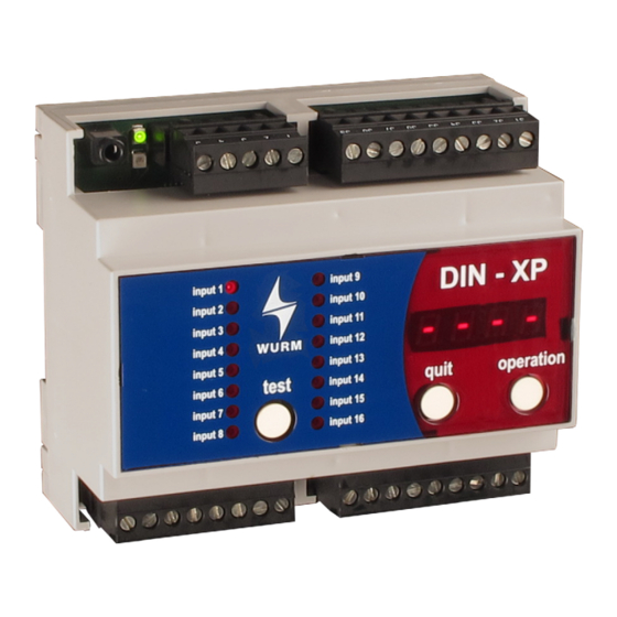
Front view
Features
Inputs for 230V~
Individual selection of operating input or fault input
Load current / zero signal current principle for each input
Setting of priority for all fault inputs
Alarm delay time for all fault inputs
Clear display of signal statuses and voltage statuses
Lamp test and fault message acknowledgement
Simple parameter settings
Alarm relays for priority 1 and 2 available
Selectable relay operating mode
Plug-in screw terminals
Large data memory for signal history
Clear text designations in FRIGODATA XP per input
Evaluation of Prio 1 and Prio 2 subsection faults from a gateway
Direct connection of a CAN-USB to the service socket
Connection to the Wurm system through a Wurm CAN communication bus (C-BUS) and
FRIGODATA XP
DIN-XP_V2.7.0_PI_2019-04_EN
with 16 operation or fault inputs
Subject to technical changes
DIN-XP
Input module
Page 1 of 4
Advertisement

Related Manuals for WURM DIN-XP


Summary of Contents for WURM DIN-XP
- Page 1 Evaluation of Prio 1 and Prio 2 subsection faults from a gateway Direct connection of a CAN-USB to the service socket Connection to the Wurm system through a Wurm CAN communication bus (C-BUS) and FRIGODATA XP DIN-XP_V2.7.0_PI_2019-04_EN Subject to technical changes...
- Page 2 Wurm GmbH & Co. KG Elektronische Systeme. Keep these instructions ready to hand for quick reference and pass them on with the device if the product is sold.
- Page 3 DIN-XP Input module with 16 operation or fault inputs Circuit diagram C-BUS interface Alarm relay Digital inputs Installing and connecting WARNING Danger to life from electric shock and/or fire! Switch off the power to the entire plant when carrying out installation, wiring or removal work.
- Page 4 DIN-XP Input module with 16 operation or fault inputs Place the device with the upper guide edge on the top-hat rail. Then press the device gently downward until it engages with the fastening safety catch on the top-hat rail. For wiring of the data lines, we recommend the use of standard telephone lines 2x2x0.8ø. up to lengths of 100m.
Need help?
Do you have a question about the DIN-XP and is the answer not in the manual?
Questions and answers