Table of Contents
Advertisement
Quick Links
Advertisement
Table of Contents

Summary of Contents for Neousys Nuvo-2700DS
- Page 1 Neousys Technology Inc. Nuvo-2700DS User Manual Revision 1.1...
-
Page 2: Table Of Contents
Introduction Product Specifications ..................... 11 1.1.1 Nuvo-2700DS ....................11 Dimension ......................... 12 1.2.1 Top View of Nuvo-2700DS ................12 1.2.2 Front View of Nuvo-2700DS ................12 1.2.3 Rear View of Nuvo-2700DS ................13 1.2.4 Side View of Nuvo-2700DS ................13 Wall-mount Installed Dimensions ................ - Page 3 M.2 2230 E Key Installation ................49 Installing the System Enclosure ................51 Mounting Nuvo-2700DS ................... 53 3.4.1 Wall-mounting Nuvo-2700DS (Optional Accessory) .......... 53 Powering On the System ..................54 3.5.1 Powering On Using the Power Button ............... 54 3.5.2 Powering On Using Wake-on-LAN ..............
-
Page 4: Legal Information
For questions in regards to hardware/ software compatibility, customers should contact Neousys Technology Inc. sales representative or technical support. To the extent permitted by applicable laws, Neousys Technology Inc. shall NOT be responsible for any interoperability or compatibility issues that may arise when (1) products, software, or options not certified and supported;... -
Page 5: Contact Information
3384 Commercial Avenue, Northbrook, IL 60062, USA (Illinois, USA) Tel: +1-847-656-3298 Email, Website China Neousys Technology China Co., Ltd. Room 429 /431, Building 32, Guiping Road 680, Shanghai, 200233, China Tel: +86-2161155366 Email, Website Declaration of Conformity This equipment has been tested and found to comply with the limits for a Class A digital device, pursuant to part 15 of the FCC Rules. -
Page 6: Copyright Notice
Disclaimer This manual is intended to be used as an informative guide only and is subject to change without prior notice. It does not represent commitment from Neousys Technology Inc. Neousys Technology Inc. shall not be liable for any direct, indirect, special, incidental, or consequential damages arising from the use of the product or documentation, nor for any infringement on third party rights. -
Page 7: Safety Precautions
24Vdc, 16A, Tma 60 degree C and 5000m altitude during operation. If further assistance is required, please contact Neousys Technology If the system is not going to be used for a long time, disconnect it from mains... -
Page 8: Service And Maintenance
Service and Maintenance/ ESD Precautions Service and Maintenance ONLY qualified personnel should service the system Shutdown the system, disconnect the power cord and all other connections before servicing the system When replacing/ installing additional components (expansion card, memory module, etc.), insert them as gently as possible while assuring proper connector engagement ESD Precautions... -
Page 9: About This Manual
About This Manual About This Manual This guide introduces Neousys Nuvo-2700DS system featuring the AMD Ryzen Embedded V1605B CPU and Vega GPU. It is a compact fanless 4K interactive digital signage system supporting two Google Edge TPUs. The guide also demonstrates the system’s basic installation procedures. -
Page 10: Introduction
While using Nuvo-2700DS as a video wall player, the crisp HDR image creates an ultra high definition and impressive visual impact. Also, Nuvo-2700DS is a low power fanless Edge AI platform for emerging AI applications. With the AI inference capability from Edge TPU, Nuvo-2700DS creates an interactive, personalized... -
Page 11: Product Specifications
Nuvo-2700DS Product Specifications 1.1.1 Nuvo-2700DS System Core Processor AMD Ryzen™ Embedded V1605B CPU (4C/ 8T, 2M Cache, 2.0/ 3.6 GHz,12W - 25W TDP) Graphics Vega GPU with 8 compute units Memory Up to 64 GB DDR4 2400 SDRAM (two SODIMM slots) -
Page 12: Dimension
Nuvo-2700DS Series Dimension NOTE All measurements are in millimeters (mm). 1.2.1 Top View of Nuvo-2700DS 1.2.2 Front View of Nuvo-2700DS... -
Page 13: Rear View Of Nuvo-2700Ds
Nuvo-2700DS 1.2.3 Rear View of Nuvo-2700DS 1.2.4 Side View of Nuvo-2700DS... -
Page 14: Wall-Mount Installed Dimensions
Nuvo-2700DS Series Wall-mount Installed Dimensions 1.3.1 Top View with Wall-mount Installed 1.3.2 Front View with Wall-mount Installed... -
Page 15: Rear View With Wall-Mount Installed
Nuvo-2700DS 1.3.3 Rear View with Wall-mount Installed 1.3.4 Side View with Wall-mount Installed 1.3.5 Bottom View with Wall-mount Installed... -
Page 16: System Overview
Nuvo-2700DS Series System Overview Upon receiving and unpacking your Nuvo-2700DS, please check immediately if the package contains all the items listed in the following table. If any item(s) are missing or damaged, please contact your local dealer or Neousys Technology. -
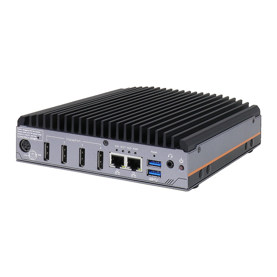
Page 17: Front Panel I/O
Nuvo-2700DS Front Panel I/O The Nuvo-2700DS I/O panel features two gigabit Ethernet, two USB3.1 Gen1, four DisplayPort ports. Item Description DC input Mini DIN for 12V DC input CMOS reset Use this button to manually reset the CMOS DisplayPort The four DisplayPort ports support 4K UHD resolution per port. -
Page 18: Dc Input
Nuvo-2700DS Series 2.2.1 DC Input The system accepts a DC power input of 12V. DO NOT plug in the 12V DC connector and the 3-pin terminal connector. The system only requires one or the other for operation. WARNING Please make sure the voltage of DC power is correct before you connect it to the system. -
Page 19: Displayport
Nuvo-2700DS 2.2.3 DisplayPort The system has four DisplayPort (DP) outputs which are digital display interfaces that mainly connect video source and carry audio to a display device. When connecting a DP, it can deliver up to 4K UHD (4096 x 2304) in resolution. The system is designed to support passive DP adapter/ cable. -
Page 20: System Status Led
Nuvo-2700DS Series 2.2.4 System Status LED There are four LED indicators on the I/O panel: PWR, WDT, HDD and IGN. The descriptions of these LEDs are listed in the following table. Indicator Color Description Green Power indictor, lid when system is on Yellow Watchdog timer LED, flashing when watchdog timer is started. -
Page 21: Ethernet Port
Nuvo-2700DS 2.2.5 Ethernet Port ® The system offers two GbE ports implemented with Intel I210-IT controllers. Each port has one dedicated PCI Express link for maximum performance. When an Ethernet connection is established, the LED indicators on the RJ45 connector represents the following connection... -
Page 22: Usb3.1 Gen1 Ports
Nuvo-2700DS Series 2.2.7 USB3.1 Gen1 Ports The system offers two USB 3.1 Gen1 (SuperSpeed USB) ports on its front panel with screw-lock mechanism. They are backward-compatible with USB 2.0, USB 1.1 and USB 1.0 devices. Legacy USB support is also provided so you can use USB keyboard/mouse in DOS environment while USB 3.1 Gen1 driver is supported natively in Windows 10. -
Page 23: Power Button
Nuvo-2700DS 2.2.9 Power Button The power button is a non-latched switch for ATX mode on/off operation. Press to turn on the system, PWR LED should light up and to turn off, you can either issue a shutdown command in the OS, or just press the power button. In case of system halts, you can press and hold the power button for 5 seconds to force-shutdown the system. -
Page 24: Rear Panel I/O
Nuvo-2700DS Series Rear Panel I/O On the rear panel of the system, you will find a 3-pin terminal block for DC input with ignition control, a DB9 COM port, a RJ50 COM port, two USB2.0 ports and an optional digital input/ output DB15 connector. -
Page 25: Usb2.0 Ports
Nuvo-2700DS 2.3.1 USB2.0 Ports The system has two USB 2.0 ports. They are implemented by native xHCI (eXtensible Host Controller Interface) controller in H310 chipset and are compatible with USB 2.0, USB 1.1 and USB 1.0 devices. Legacy USB support is also provided so you can use USB keyboard/mouse in DOS environment. -
Page 26: Com1 Port
Nuvo-2700DS Series 2.3.3 COM1 Port The system provides two COM ports for communicating with external devices. These COM ports are implemented using industrial-grade ITE8786 Super IO chip (-40 to 85°C) and provide up to 115200 bps baud rate. COM1 and COM2 are software-configurable RS-232/422/485 ports. The operation mode of COM1 and COM2 can be set in BIOS setup utility. -
Page 27: Digital Io Port (Optional)
Nuvo-2700DS 2.3.4 Digital IO Port (Optional) The system features an optional digital IO port that has 4x isolated digital input channels and 4x isolated digital output channels. The DIO functions support polling mode I/O access and DI change-of-state interrupt. Please refer to Watchdog Timer &... -
Page 28: 3-Pin Terminal Block Dc Input
Nuvo-2700DS Series 2.3.5 3-pin Terminal Block DC Input The system accepts a wide range of DC power input from 8 to 35V via a 3-pin pluggable terminal block, which is fit for field usage where DC power is usually provided. The screw clamping mechanism on the terminal block offers connection reliability when wiring DC power. -
Page 29: Internal I/O Functions
Nuvo-2700DS Internal I/O Functions In addition to I/O connectors on the front panel, the system also provides internal on-board expansion slots. In this section, we’ll illustrate these internal I/O functions. 2.4.1 M.2 2280 (SATA Signal Only) Slot for SSD The system has an M.2 2280 slot (SATA signal only) for you to install an M.2 SATA SSD for faster access over traditional hard disk drives. - Page 30 Nuvo-2700DS Series M.2 2280 M Key Pin Definition Pin # Signal Pin # Signal +3V3 +3V3 DAS/DSS_N +3V3 +3V3 +3V3 +3V3 DEVSLP SATA-B+ SATA-B- SATA-A- SATA-A+ PERST N Mechanical Key SUSCLK PEDET +3V3 +3V3 +3V3...
-
Page 31: Dual Dram So-Dimm Slot
Nuvo-2700DS 2.4.2 Dual DRAM SO-DIMM Slot DRAM slot, bottom panel side DRAM slot, heatsink side The system motherboard supports two 260-pin SODIMM socket for installing two DDR4-2400 memory modules up to 64GB capacity. -
Page 32: M.2 3042/ 3052 B Key Socket
Nuvo-2700DS Series 2.4.3 M.2 3042/ 3052 B Key Socket The system has one M.2 3042/ 3052 B key socket (in blue) with USB3.1 Gen 1 and USB 2.0 signal for 4G/ 5G module installation. There is also a corresponding micro-SIM SIM card slot (in red). - Page 33 Nuvo-2700DS M.2 3042/ 3052 B Key Pin Definition Pin # Signal Pin # Signal +3V3 +3V3 FULL_CARD_POWER_OFF_N USB_D+ W_DISABLE_N USB_D- Mechanical Key USB3.0-RX- USB3.0-RX+ UIM1-RESET UIM1-CLK USB3.0-TX- UIM1-DATA USB3.0-TX+ UIM1-PWR PERST_N RESET_N CONFIG_1 +3V3 +3V3 +3V3...
-
Page 34: 2230 E Key Socket
Nuvo-2700DS Series 2.4.4 M.2 2230 E Key Socket The system has an M.2 2230 E key socket that offers PCIe Gen3 x1 and USB2.0 signal for WiFi module installation. For SMA antenna installation, there are two dedicated openings located on both side of the chassis. - Page 35 Nuvo-2700DS M.2 2230 E Key Pin Definition Pin # Signal Pin # Signal +3V3 USB_D+ +3V3 USB_D- Mechanical Key PETP0 PETN0 PER P0 PER N0 REFCLK_P0 REFCLK_N0 CLKREQ# PERST# W_DISABLE# +3V3 +3V3...
-
Page 36: Ignition Rotary Switch
Nuvo-2700DS Series 2.4.5 Ignition Rotary Switch The system features an ignition control switch that has multiple modes for pre and post ignition settings. Please refer to the section Ignition Power Control for details. -
Page 37: Dual Half-Mini Pcie Socket
Nuvo-2700DS 2.4.6 Dual Half-mini PCIe Socket The dual half-size mini-PCIe sockets are for installing Google Edge Tensor Processing Unit (TPU). They are ideal for machine learning applications or large complex neural network models that can take up to weeks to compute but requiring only a few hours on Google... - Page 38 Nuvo-2700DS Series mini-PCIe slot definition Pin # Signal Pin # Signal WAKE# +3.3Vaux +1.5V CLKREQ# REFCLK- REFCLK+ Mechanical Key Reserved* (UIM_C8) Reserved* (UIM_C4) W_DISABLE# PERST# PCIe_Rxn +3.3Vaux PCIe_Rxp +1.5V SMB_CLK PCIe_Txn SMB_DATA PCIe_Txp +3.3V +3.3V Reserved Reserved +1.5V Reserved +3.3V...
-
Page 39: Ignition Rotary Switch
Nuvo-2700DS 2.4.7 Ignition Rotary Switch The ignition power control switch features multiple modes for pre and post ignition settings. Please refer to the section Ignition Power Control for details. -
Page 40: System Installation
Nuvo-2700DS Series System Installation Before disassembling the system enclosure and installing components and modules, please make sure you have done the following: It is recommended that only qualified service personnel should install and service this product to avoid injury or damage to the system. -
Page 41: Disassembling The System
Nuvo-2700DS Disassembling the System To access system internal components, the system needs to be disassembled. To disassemble the system enclosure, please refer to the procedures below: Turn the system upside-down on a steady surface. Remove the screws indicated and separate the bottom panel from the system’s enclosure. - Page 42 Nuvo-2700DS Series Remove the screw indicated on the rear I/O panel. Remove the screw indicated on the front I/O panel. Remove the screws from both sides of the chassis. Left side chassis screws Right side chassis screws The four side of the enclosure can now be separated into a faceplate and a rear...
- Page 43 Nuvo-2700DS To separate the motherboard from the heatsink, please remove the screws indicated. Gently lift the motherboard to separate it from the heatsink. Turn the motherboard around to gain access to the second DRAM module slot (in blue) and dual half-size mini-PCIe expansion slots (in red) for TPU module installation.
-
Page 44: Installing Internal Components
Nuvo-2700DS Series Installing Internal Components 3.2.1 DDR4 SO-DIMM Installation There are two memory SO-DIMM slots on the motherboard that supports up to 64GB DDR4-2400. Please follow the procedures below to replace or install the memory modules. 1. Please refer to the section “Disassembling the... - Page 45 Nuvo-2700DS 4. Push the memory module down until it is clipped-in. Reinstall the system enclosure and panel when done. If you need to install other components, please refer to respective sections.
-
Page 46: 2280 Ssd Installation
Nuvo-2700DS Series 3.2.2 M.2 2280 SSD Installation The system has an SATA signal M.2 2280 slot for you to install an M.2 2280 SATA SSD. For installation, please refer to the following instructions. The M.2 slot can be accessed by removing the bottom panel. Please refer to the section “Disassembling the... -
Page 47: 3042/ 3052 B Key Installation
Nuvo-2700DS 3.2.3 M.2 3042/ 3052 B Key Installation The M.2 3042/ 3052 B key slot (indicated in blue) has a corresponding micro-SIM SIM card slot (indicated in red). The M.2 slot can be accessed by removing the bottom panel. Please refer to the section “Disassembling the... - Page 48 Nuvo-2700DS Series Gently place the micro-SIM SIM card in the orientation shown, lower the cover and slide the cover in the direction shown to secure the SIM card in place. Place into socket with orientation shown Slide cover to secure the micro-SIM To install the M.2 3042/ 3052 module into place, insert the module on a 45°...
-
Page 49: 2230 E Key Installation
Nuvo-2700DS 3.2.4 M.2 2230 E Key Installation The system has an M.2 2230 E key socket that offers PCIe Gen3 x1 and USB2.0 signal for WiFi module installation. The M.2 slot can be accessed by removing the bottom panel. Please refer to the section “Disassembling the... - Page 50 Nuvo-2700DS Series module and secure the antenna to the side panel. Please refer to the module’s manual for clip-on connection. Secure on side panel Antenna installation Reinstall the system enclosure, panel and external antenna. If you need to install other components, please refer to respective sections.
-
Page 51: Installing The System Enclosure
Nuvo-2700DS Installing the System Enclosure To reinstall the system enclosure, please follow the steps below: Slide the motherboard and heatsink back into the U-shaped enclosure and secure it with four screws on top of the heatsink. Screws locations on the heatsink Lower the motherboard matching the screw holes The enclosure panels consist of front and rear sections. - Page 52 Nuvo-2700DS Series Left side chassis screws securing the heatsink Right side chassis screws securing the heatsink Secure the screws indicated to complete the enclosure installation.
-
Page 53: Mounting Nuvo-2700Ds
Wall-mounting Nuvo-2700DS (Optional Accessory) Nuvo-2700DS systems have built-in wall-mounting brackets as the standard mounting option. Please follow steps below to mount your Nuvo-2700DS controller on a flat surface. Take the two wall mount brackets and four M4 screws out of the accessory box, secure the wall mount brackets according to the illustration shown below. -
Page 54: Powering On The System
There are three methods to power on the system Pressing the power button Sending a LAN packet via Ethernet (Wake-on-LAN) Powering on via ignition control (for Nuvo-2700DS-IGN only, please refer to Ignition Control section) 3.5.1 Powering On Using the Power Button This is the simplest way to turn on your system. -
Page 55: Powering On Using Wake-On-Lan
Nuvo-2700DS 3.5.2 Powering On Using Wake-on-LAN Wake-on-LAN (WOL) is a mechanism to wake up a computer system from a S5 (system off with standby power) state via issuing a magic packet. The system’s Wake-on-LAN compatible GbE port is shown below. - Page 56 Nuvo-2700DS Series Magic Packet The magic packet is a broadcast frame containing anywhere within its payload 6 bytes of all 255 (FF FF FF FF FF FF in hexadecimal), followed by sixteen repetitions of the target computer's 48-bit MAC address.
-
Page 57: Ignition Power Control
Nuvo-2700DS Ignition Power Control The ignition power control module for in-vehicle applications is a MCU-based implementation that monitors the ignition signal and reacts to turn on/off the system according to predefined on/off delay. Its built-in algorithm supports other features such as ultra-low power standby, battery-low protection, system hard-off, etc. -
Page 58: Additional Features Of Ignition Power Control
Nuvo-2700DS Series 3.6.2 Additional Features of Ignition Power Control In addition to the typical timing correlation, the ignition power control module offers additional features to provide additional reliability for in-vehicle applications. 1. Low battery detection The ignition power control module continuously monitors the voltage of DC input when the system is operational. -
Page 59: Wiring Ignition Signal
Nuvo-2700DS 3.6.3 Wiring Ignition Signal To have ignition power control for in-vehicle usage, you need to supply IGN signal to the system. The IGN input is located on the 3-pin pluggable terminal block (shared with DC power input). Below is the typical wiring configuration for in-vehicle applications. -
Page 60: Configure Your Windows System
Nuvo-2700DS Series 3.6.4 Configure your Windows system When applying ignition power control to your system, please make sure you’ve configured your Windows system to initiate a shutdown process when pressing the power button. By default, Windows 7/ 8/ 10 goes to sleep (S3) mode when power button is pressed. As sleep... -
Page 61: Operation Modes Of Ignition Power Control
Nuvo-2700DS 3.6.5 Operation Modes of Ignition Power Control You can use the rotary switch to configure the operation mode. The system offers 16 (0~15) operation modes with different power-on/power-off delay configurations. The ignition control rotary switch can be located on the motherboard. Please refer to the “Disassembling the enclosure”... - Page 62 Nuvo-2700DS Series Mode 3 ~ Mode 12 Mode 3 ~ Mode 12 have various power-on delay and power-off delay. Each mode supports a hard-off timeout of 10 minutes. Mode Power-on Delay Power-off Delay Hard-off Timeout 10 seconds 10 seconds...
-
Page 63: System Configuration
NOTE Not all BIOS settings will be discussed in this section. If there is a particular BIOS setting you are after but is not discussed in this section, please contact Neousys Technical Support staff. -
Page 64: Com1 & Com2 Configuration
Nuvo-2700DS Series 4.1.1 COM1 & COM2 Configuration The system’s COM1/ COM2 ports support RS-232 (full-duplex) mode. You can enable/ disable both COM ports via BIOS settings. To set COM port operating mode: Press F2when the system boots up to enter the BIOS setup utility. -
Page 65: Chipset Configuration (Pcie Root Port For Tpu)
Nuvo-2700DS 4.1.2 Chipset Configuration (PCIe Root Port for TPU) If you are installing Google Tensor Processing Unit (TPU) into the half-size mini-PCIe slots, you may enable and configure the slot in the BIOS. To configure PCIe Root Port (TPU): 1. When system boots up, press F2 to enter BIOS setup utility. -
Page 66: Power On After Power Failure Option
Nuvo-2700DS Series 4.1.3 Power On After Power Failure Option This option defines the behavior of system when DC power is supplied. Value Description S0 – Power On System is powered on when DC power is supplied. S5 – Power Off System is kept in off state when DC power is supplied. -
Page 67: System Power Configuration
Nuvo-2700DS 4.1.4 System Power Configuration The system supports various AMD Ryzen Embedded V1605B CPU, the configuration “System Power Configuration” is implemented in BIOS to allow users to specify user-defined power limit. This feature gives you the flexibility of selecting different power performance while balance between computing power and operating temperature range. -
Page 68: Wake On Lan Option
Nuvo-2700DS Series 4.1.5 Wake on LAN Option Wake-on-LAN (WOL) is a mechanism which allows you to turn on your system via Ethernet connection. To utilize Wake-on-LAN function, you have to enable this option first in BIOS settings. Please refer to “Powering On Using Wake-on-LAN” to set up the system. -
Page 69: Boot Menu
Nuvo-2700DS 4.1.6 Boot Menu The Boot menu in BIOS allows you to specify the system’s boot characteristics by setting bootable device components (boot media) and method. Or, you may press F12 upon system start up and select a device you wish boot from. -
Page 70: Boot Type (Legacy/ Uefi)
Nuvo-2700DS Series 4.1.7 Boot Type (Legacy/ UEFI) The system supports both Legacy and Unified Extensible Firmware Interface (UEFI) boot modes. UEFI is a specification proposed by Intel to define a software interface between operating system and platform firmware. Most modern operating systems, such as Windows 7/8/10 and Linux support both Legacy and UEFI boot modes. -
Page 71: Add Boot Options
Nuvo-2700DS 4.1.8 Add Boot Options The Add Boot Options dedicates the boot sequence order of a newly added device (eg. USB flash drive). The setting allows you to set the newly added device to boot first or as the last device on the list. -
Page 72: Watchdog Timer For Booting
Nuvo-2700DS Series 4.1.9 Watchdog Timer for Booting The Watchdog timer setting in the BIOS ensures a successful system boot by specifying a timeout value. If the Watchdog timer is not stopped and expires, the BIOS will issues a reset command to initiate another boot process. There are two options in BIOS menu, “Automatically after POST”... -
Page 73: 4.1.10 Legacy/ Uefi Boot Device
Nuvo-2700DS 4.1.10 Legacy/ UEFI Boot Device When you wish to set a designated boot device, you may set it as the first device to boot in Legacy or UEFI Boot Device setting. Or if you wish to manually select a boot device, you may do so by pressing F12 when the system boots up. -
Page 74: Os Support And Driver Installation
I210 GbE controller if the driver is not embedded in kernel. You can visit AMD website for further information. Neousys may remove or update operating system compatibility without prior notice. Please contact us if your operating system of choice is not on the list. -
Page 75: Driver Installation
Nuvo-2700DS Driver Installation To manually install the drivers, please click on this link to download the drivers. 5.2.1 Install Drivers Manually Please note when installing drivers manually, you need to install the drivers in the following sequence mentioned below. Windows 10 (x64) The recommended driver installation sequence is Chipset driver (x:\Driver_Pool\Chipset_CFL\Win_10_64\SetupChipset.exe) -
Page 76: Driver Installation For Watchdog Timer Control
Nuvo-2700DS Series Driver Installation for Watchdog Timer Control Neousys provides a driver package which contain function APIs for Watchdog Timer control function. You should install the driver package (WDT_DIO_Setup.exe) in prior to use these functions. Please note that you must install WDT_DIO_Setup_v2.3.0.0 or later versions. -
Page 77: Appendix A Using Wdt & Dio
WDT and keep resetting the timer to make sure the system or program is running. Otherwise, the system shall be reset. In this section, we’ll illustrate how to use the function library provided by Neousys to program the WDT functions. Currently, WDT driver library supports Windows 7/ 8.1/ 10 32-bit and 64-bit versions. -
Page 78: Wdt And Dio Library Installation
Nuvo-2700DS Series WDT and DIO Library Installation To setup WDT & DIO Library, please follow instructions below. 1. Execute WDT_DIO_Setup.2.3.0.xexe. and the following dialog appears. 2. Click “Next >” and specify the directory of installing related files. The default directory is... - Page 79 Nuvo-2700DS 3. Once the installation has finished, a dialog will appear to prompt you to reboot the system. The WDT & DIO library will take effect after the system has rebooted. 4. When programming your WDT or DIO program, the related files are located in...
-
Page 80: Wdt Functions
Nuvo-2700DS Series WDT Functions InitWDT BOOL InitWDT(void); Syntax Description: Initialize the WDT function. You should always invoke InitWDT() before set or start watchdog timer. None Parameter Return Value TRUE: Successfully initialized FALSE: Failed to initialize Usage BOOL bRet = InitWDT() SetWDT BOOL SetWDT(WORD tick, BYTE unit);... -
Page 81: Startwdt
Nuvo-2700DS StartWDT Syntax BOOL StartWDT(void); Description Starts WDT countdown. Once started, the WDT LED indicator will begin blinking. If ResetWDT() or StopWDT is not invoked before WDT countdowns to 0, the WDT expires and the system resets. Parameter None Return Value... -
Page 82: Dio Functions
Nuvo-2700DS Series DIO Functions InitDIO Syntax BOOL InitDIO(void); Initialize the DIO function. You should always invoke InitDIO() Description before write/read any DIO port/channel. Parameter None Return Value Returns TRUE if initialization successes, FALSE if initialization failed. BOOL bRet = InitWDT() -
Page 83: Dowriteline
Nuvo-2700DS DOWriteLine Syntax void DOWriteLine(BYTE ch, BOOL value); Write a single channel of isolated digital output. Description Parameter BYTE value specifies the DO channel to be written. Ch should be a value of 0 ~ 7. value BOOL value (TRUE or FALSE) specifies the status of DO channel.