
Related Manuals for ADLINK Technology MCM-204

Summary of Contents for ADLINK Technology MCM-204
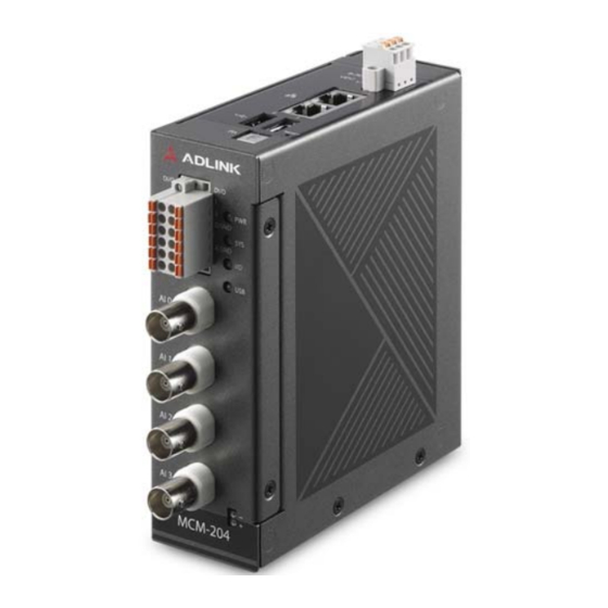
- Page 1 MCM-204 Standalone Ethernet DAQ for Distributed Machine Condition Monitoring User’s Manual Manual Rev.: Revision Date: January 14, 2020 Part No: 50-1Z301-1000 Leading EDGE COMPUTING...
- Page 2 Leading EDGE COMPUTING Revision History Revision Release Date Description of Change(s) 2020-01-14 Initial Release...
- Page 3 MCM-204 Preface Copyright © 2020 ADLINK Technology Inc. This document contains proprietary information protected by copy- right. All rights are reserved. No part of this manual may be repro- duced by any mechanical, electronic, or other means in any form without prior written permission of the manufacturer.
- Page 4 Leading EDGE COMPUTING California Proposition 65 Warning WARNING: This product can expose you to chemicals including acrylamide, arsenic, benzene, cadmium, Tris(1,3-dichloro-2-propyl)phosphate (TDCPP), 1,4-Diox- ane, formaldehyde, lead, DEHP, styrene, DINP, BBP, PVC, and vinyl materials, which are known to the State of California to cause cancer, and acrylamide, benzene, cadmium, lead, mercury, phthalates, toluene, DEHP, DIDP, DnHP, DBP, BBP, PVC, and vinyl materials, which are known to the State of California to cause...
-
Page 5: Table Of Contents
Reset Pin for Factory Default ........15 1.5.5 Ethernet Ports............16 1.5.6 LED Indicators ............16 1.5.7 USB Ports..............16 2 Getting Started ..............17 Unpacking the MCM-204 ........... 17 Connecting to I/O............... 17 Connecting/Disconnecting Power........18 Checking Device Status............. 18 Table of Contents... - Page 6 Leading EDGE COMPUTING Usage Scenarios..............18 2.5.1 First-Time Configuration / Portable DAQ ....19 2.5.2 Periodic Polling (REST API) ........19 2.5.3 Continuous Data (Streaming SDK)......19 2.5.4 Passive Data (TCP Socket) ........19 3 Web Console ..............21 Web Console Login............21 Web Console Menu ............
-
Page 7: List Of Figures
MCM-204 List of Figures Figure 1-1: Front View ..............6 Figure 1-2: Top View..............7 Figure 1-3: Left Side View............. 8 Figure 1-4: Right Side View ............9 Figure 1-5: DIN Rail Mount Dimensions ........10 Figure 1-6: Wall Mount Dimensions..........11 Figure 1-7: Wall Mount Assembly .......... - Page 8 Leading EDGE COMPUTING This page intentionally left blank. viii List of Figures...
-
Page 9: Introduction
By capturing data such as FFT, power spectrum, overall value (OA), etc., with a standalone DAQ, the MCM-204 plays a critical role in pre-process- ing at the edge. Continuous high-volume data generated in the field can be converted to filtered data, significantly reducing its size. -
Page 10: Features
Leading EDGE COMPUTING 1.1 Features Standalone Ethernet DAQ for edge computing RESTful API reports machine conditions to IT system Streaming SDK for continuous data acquisition Built-in web console for easy configuration and to facilitate its use as a portable DAQ ... -
Page 11: Specifications
MCM-204 1.3 Specifications 1.3.1 General Specifications System Specifications Ethernet (1 Gb) 2x RJ-45 Ethernet ports (1 IP, Ethernet cascade when powered on) ARM Cortex A9 1.0 GHz NAND Flash (eMMC) 4 GB Memory DDR3 RAM 1 GB 2x USB 2.0 (for Wi-Fi dongle only) -
Page 12: Isolated Digital I/O
Leading EDGE COMPUTING Analog Input Specifications AC Cut-off Frequency 0.4 Hz (-3dB) AC Cut-off Frequency 2.4 Hz (-0.1dB) Trigger Sources Software, digital trigger, analog trigger, built-in button Overvoltage Protection ±50 V Input Impedance 200 kΩ between positive input and negative input 115 Ω... -
Page 13: Mechanical
MCM-204 1.3.4 Mechanical Mechanical Specifications Dimensions 110.5 (L) x 40 (W) x 126.5 (H) mm Connectors 4x BNC + 2x 6-pin spring-type terminal block Front Panel LEDs Housing Metal, IP30 Mounting DIN rail mount kit (optional: wall mount kit, P/N 34-51112-0000) 1.3.5... -
Page 14: Mechanical Drawings
Leading EDGE COMPUTING 1.4 Mechanical Drawings 1.4.1 Dimensions Units: mm 126.5 Figure 1-1: Front View Introduction... -
Page 15: Figure 1-2: Top View
MCM-204 Units: mm 111.65 Figure 1-2: Top View Introduction... -
Page 16: Figure 1-3: Left Side View
Leading EDGE COMPUTING 111.65 Units: mm 126.5 Figure 1-3: Left Side View Introduction... -
Page 17: Figure 1-4: Right Side View
MCM-204 111.65 Units: mm 126.5 Figure 1-4: Right Side View Introduction... -
Page 18: Din Rail Mount
Leading EDGE COMPUTING 1.4.2 DIN Rail Mount The DIN rail mount may be attached to the MCM-204 using two flat head screws (included). Units: mm 89.18 80.43 78.38 70.75 41.1 Figure 1-5: DIN Rail Mount Dimensions Introduction... -
Page 19: Wall Mount
MCM-204 1.4.3 Wall Mount The optional wall mount bracket may be attached to the MCM-204 via four pan head screws (included with wall mount kit, P/N 34-51112-0000; see also Figure 1-7 on page 12). 80.0 Units: mm 61.6 20.0 70 100 106 Ø... -
Page 20: Figure 1-7: Wall Mount Assembly
Leading EDGE COMPUTING Figure 1-7: Wall Mount Assembly Introduction... -
Page 21: I/O Connectors
4 LED indicator lights 1.5.1 Analog Input BNC Connector The MCM-204 module is equipped with four BNC connectors to receive voltage signals from various sources. For sensors requir- ing excitation, such as accelerometers or microphones, the IEPE excitation current can be enabled to reduce the wiring effort. -
Page 22: Digital Input And Output
1.5.3 Temperature Sensor Input The MCM-204 allows you to monitor the temperature of a target device or environment between -50 to 150°C using the tempera- ture sensor provided. Connect the temperature sensor leads to the connector as shown. -
Page 23: Reset Pin For Factory Default
MCM-204 1.5.4 Reset Pin for Factory Default Restore the MCM-204 to its factory default settings using a paper clip or similar item inserted into the reset pin hole button and pressing the reset button for three seconds until the device reboots. -
Page 24: Ethernet Ports
Leading EDGE COMPUTING 1.5.5 Ethernet Ports The MCM-204 has two GbE ports with one MAC address. Either port can be used for connecting to a host PC, leaving the second port available for cascading. The default static IP address is 169.254.1.1. -
Page 25: Getting Started
Ethernet port to cascade them together. Cascading reduces the number of ports needed to connect devices. If connecting MCM-204 devices in a daisy chain, only use a sequence configuration: do not use a ring configuration. A ring configuration will cause network communications to fail. -
Page 26: Connecting/Disconnecting Power
2. Turn on the power source. If the power was connected correctly, the front panel red PWR LED will light up. If the MCM-204 needs to be shut down, turn off the power source. To remove the power wires, use a flat head screwdriver to push the orange slots on the terminal block and then pull out the wires. -
Page 27: First-Time Configuration / Portable Daq
Many distributed machine condition monitoring applications acquire device status periodically, for example, every minute, or hourly. The MCM-204 retains captured data in the REST data for- mat. Especially in IT systems, user applications frequently adopt REST APIs because they are intuitive. The MCM-204 emulates all... - Page 28 Leading EDGE COMPUTING This page intentionally left blank. Getting Started...
-
Page 29: Web Console
Option 1: IP Address In the web browser’s address bar, enter the MCM-204’s IP address (e.g., http://169.254.1.1). The default network setting of the MCM-204 is Static IP mode with an IP address of 169.254.1.1. Option 2: Hostname Connect the MCM-204 to a network component (switch/router) with DNS functionality, then enter the MCM-204’s hostname in... -
Page 30: Web Console Menu
Leading EDGE COMPUTING Figure 3-1: Web Console Login Page 3.2 Web Console Menu The web console menu bar includes the following items. System Information Device Setting Data Capture Peripheral Data History Data Condition Mission Management ... -
Page 31: Figure 3-2: Web Console Welcome Page
MCM-204 Figure 3-2: Web Console Welcome Page Depending on the host PC screen size and resolution, the menu list might be collapsed. Click the menu icon to expand the menu. Figure 3-3: Menu Icon Web Console... -
Page 32: System Information
Leading EDGE COMPUTING 3.2.1 System Information The System Information page shows the device software version, general information, I/O channel status, and network status. Figure 3-4: System Information Web Console... -
Page 33: Peripheral
MCM-204 3.2.2 Peripheral Peripheral digital input/output and temperature sensor information is shown on this page. The Status area shows the current status of the peripherals. Select REFRESH to update the status. Four digital input/output devices can be used. Each can be adjusted for either input or output mode. -
Page 34: Data History
Mission Management A mission is a setting of I/O parameters with an intended output method. The MCM-204 will execute the same settings even after a reboot, so if Repeat Times is set to 0 (endless data capture), the MCM-204 will run its previous mission after reboot. To configure the I/O parameters for another mission, delete the current mission. -
Page 35: Change Password
MCM-204 3.2.5 Change Password This page is used to change the password of each MCM-204, whether there is a single device or multiple daisy chained devices. It is recommended that each device have a unique password since the default password for every MCM-204 is identical. -
Page 36: System Setting
Leading EDGE COMPUTING 3.2.7 System Setting This page manages various system settings. Hostname: The device’s hostname can be modified by entering a new hostname here and clicking the APPLY button. A hostname can be used instead of an IP address to access a specific device’s web console. -
Page 37: Figure 3-11: System Settings
MCM-204 Data Keep: By default, the MCM-204 stores history data only in RAM and the data is lost when the system reboots. Select Enable to also save history data to internal storage. The amount of disk space allocated for this purpose is 300MB. When that limit is... -
Page 38: Figure 3-12: Upload Customization/Firmware Files
Leading EDGE COMPUTING Customization Library Upload: This function runs custom formu- las on the MCM-204 according to a given file. See “Custom Filter- ing Algorithms” on page 42. Firmware Upgrade: A firmware upgrade file can be uploaded to the MCM-204 through this feature. These files will periodically be provided through the product web page: www.adlinktech.com/Products/IoT_solutions/Smart_Factory/MCM-204... -
Page 39: Tcp Socket
MCM-204 3.2.8 TCP Socket The MCM-204 supports TCP socket communication as a socket client. Enter the IP address and port number of the remote TCP socket server. Different analog input channels can be mapped to different ports. Select ADD RULE to add the TCP server to the Socket Connection List. -
Page 40: Daq Mission
Leading EDGE COMPUTING 3.3 DAQ Mission The MCM-204 performs excellent vibration detection with an ana- log IEPE accelerator connected. Related parameters can be set via the Device Setting page. Figure 3-14: Device Configuration Trigger Source allows the data capture function to be triggered from a particular source via analog and digital triggers. -
Page 41: Figure 3-15: Datatype
MCM-204 Repeat Times is the total number of times the data is to be cap- tured. For endlessly repeating data capture, set to 0. Warning! If you are using a customized algorithm as your Data Type, it is strongly recommended to set Repeat Times to 1 for the first attempt, then to 10 for a limited data capture test. - Page 42 Leading EDGE COMPUTING The MCM-204 has built-in functionality for several common data types and also supports user-customized data types, as detailed in the table below. If two or more data types are required for an analog input channel, select ADD DATATYPE for each additional data type.
-
Page 43: Figure 3-16: Add Condition
MCM-204 ADD CONDITION provides an event warning mechanism. When a given condition is triggered, a warning message will display on the Data Condition page. Figure 3-16: Add Condition After the desired settings have been configured, click APPLY to activate your changes. -
Page 44: Figure 3-17: Data Capture
MCM-204 devices. Click SAVE PROFILE to download the file to your PC. To import a Mis- sion Profile to an MCM-204 device, click Choose File under Select Mission Profile and select the desired configuration file. -
Page 45: Figure 3-19: Apply A New Mission
If a mission is already running while attempting to apply new changes, a confirmation window will appear. If you’re ready for the MCM-204 to cancel its previous mission and start running the new mission, click YES. Figure 3-19: Apply a New Mission... - Page 46 Leading EDGE COMPUTING This page intentionally left blank. Web Console...
-
Page 47: Daq Missions
4.1 Usage Behaviors IEPE sensors transmit raw data to the MCM-204 which can then be filtered to other kinds of data types that are more application appropriate, such as overall vibration values (ISO 10816) for mechanical vibration data. -
Page 48: Web Console
Leading EDGE COMPUTING 4.1.1 Web Console The MCM-204 has a built-in, easy-to-use web console that imple- ments all device functionalities. By logging into the web console through a connected host PC, users can see all of the device’s current settings, each feature it provides, and any vibration data it has collected. -
Page 49: Continuous Data
MCM-204 4.1.3 Continuous Data To use continuous data mode, first install the Streaming SDK, available for download on the MCM-204 product web page: www.adlinktech.com/Products/IoT_solutions/Smart_Factory/MCM-204 After installation, C/C++ sample code and function references can be found in the C:\ADLINK\MCM\MCM200 folder. Before using the Streaming SDK, DDS must be enabled via the MCM-204 web console. -
Page 50: Passive Data
The conventional message exchange pattern of the MCM-204 for Periodic Polling and Continuous Data modes is request-response, with the MCM-204 serving as responder. After receiving a query from the host, the MCM-204 responds with the requested data. However, for some applications it’s desirable for the host server to passively wait for data from the client. - Page 51 4. Run the “make” command from within the CalRMS folder to generate a customAlgo.so file. 5. Upload customAlgo.so to the MCM-204 from the web console System Setting page. 6. After it uploads, log back into the web console. DAQ Missions...
- Page 52 Leading EDGE COMPUTING 7. After logging in, choose Customization as the data type, set parameters as needed, then click APPLY to apply the task to the MCM-204. 8. Check the results on the data capture page. DAQ Missions...
-
Page 53: Important Safety Instructions
MCM-204 Important Safety Instructions For user safety, please read and follow all instructions, Warnings, Cautions, and Notes marked in this manual and on the associated device before handling/operating the device, to avoid injury or damage. S'il vous plaît prêter attention stricte à tous les avertissements et mises en garde figurant sur l'appareil , pour éviter des blessures... - Page 54 Leading EDGE COMPUTING A Lithium-type battery may be provided for uninterrupted backup or emergency power. Risk of explosion if battery is replaced with one of an incorrect type; please dispose of used batteries appropriately. Risque d’explosion si la pile est remplacée par une autre de CAUTION: type incorrect.
-
Page 55: Getting Service
San Jose, CA 95138, USA Tel: +1-408-360-0200 Toll Free: +1-800-966-5200 (USA only) Fax: +1-408-360-0222 Email: info@adlinktech.com ADLINK Technology (China) Co., Ltd. 300 Fang Chun Rd., Zhangjiang Hi-Tech Park Pudong New Area, Shanghai, 201203 China Tel: +86-21-5132-8988 Fax: +86-21-5132-3588 Email: market@adlinktech.com ADLINK Technology GmbH Hans-Thoma-Straße 11...
Need help?
Do you have a question about the MCM-204 and is the answer not in the manual?
Questions and answers