Table of Contents
Advertisement
Quick Links
Advertisement
Table of Contents

Summary of Contents for SWT UVL Series
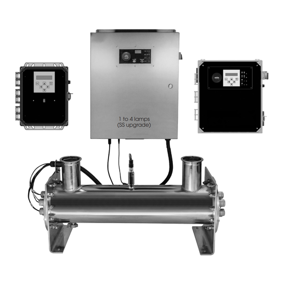
- Page 1 I N S T A L L A T I O N , O P E R A T I O N , M A I N T E N A N C E M A N U A L UVL SERIES ULTRAVIOLET WATER TREATMENT SYSTEM 1 to 4 lamps (SS upgrade)
-
Page 2: Table Of Contents
TABLE OF CONTENTS Safety Instructions . . . . . . . . . . . . . . . . . . . . . . . . . . . . . . . . . . . . . . . . . . . . . . . . . . . . . . . . . . . . . . . . . . . . . . . . . 4 1) Information . - Page 3 UVL Series Short Chambered Systems Replacement Parts . . . . . . . . . . . . . . . . .
-
Page 4: Safety Instructions
SAFETY INSTRUCTIONS In order to protect end users and operators from injury, safety precautions must be followed . This Installation, Operation and Maintenance (IOM) Manual outlines important safety issues . 1) INFORMATION Please read this manual prior to installing, starting up, and operating the equipment . The equipment uses the latest in UV technology, and has been designed to make operation and maintenance easy . -
Page 5: Major Components
3) MAJOR COMPONENTS The UV disinfection system comes with a number of components . It is recommended to inspect the unit upon arrival . a) Disinfection Chamber The chamber is manufactured from high-grade 316L stainless steel . The vessel has been passivated and electropolished to protect the vessel against aggressive high purity water . -
Page 6: D) Electronic Control Center (Ecc)
d) Electronic Control Center (ECC) The ECC is designed to be remote mounted within four to six feet of the chamber . Prior to final placement, ensure that the supplied cable lengths are adequate to reach between the ECC and the chamber . The ECC requires clean power . - Page 7 status such as individual lamp indicator, and is capable of monitoring total runtime hours, lamp runtime hours, lamp intensity, relative UV percentage, temperature, and in some models, real- time dosage . The ECC is equipped with a manual on/off switch for standard models . The optional HOA (Hands Off Auto) switch enables you to remotely power on/off your UV system .
-
Page 8: Preparation For Installing Uv System
4) PREPARATION FOR INSTALLING UV SYSTEM a) Water Quality For optimum performance of the UV system, water quality is extremely important . Proper pretreatment is essential for the UV system to operate as intended . UV disinfection dosages are dependent upon the quality and clarity of the incoming water . Impurities in the water can interfere with the UV intensity and cause the dosage to fall to unsafe levels . -
Page 9: C) Optimizing System Performance
c) Optimizing System Performance The UV lamps and their corresponding quartz sleeves need to be maintained . As a general rule, the lamps need to be changed after a year of usage (10,000 hours) . Quartz sleeves should be changed about every three (3) years or sooner if degraded and/or damaged . Quartz sleeves also need to be cleaned on a periodic basis based on real world operating conditions . -
Page 10: Installation
5) INSTALLATION Qualified professionals (contractors, plumbers, electricians) should install the mechanical and electrical components to code as per the engineering documents . a) Electronic Control Center (ECC) The ECC is supplied with either a power cord or conduit opening depending on the model . Polycarbonate Enclosures The ECC is supplied with a power cord . -
Page 11: B) Hands Off Auto Switch Wiring
b) Hands Off Auto Switch Wiring Polycarbonate and Stainless Steel Enclosure with Power Cord To wire the HOA Switch for remote access: 1 . To make installation easy, first remove the wire duct cover and unscrew the display plate (this does not need to be removed completely) to access the circuit breaker to install the incoming power wires . -
Page 12: C) Lamp Out Alert (Optional)
c) Lamp Out Alert (Optional) For models equipped with Lamp Out Alert ballast(s), connect the external control (PLC or SCADA) to the bottom of the enclosure via the auxiliary connection . WARNING: Control signal may not exceed 32VAC, 50VDC, 50mA current. d) Chamber Drawing shown Short Chambered System with 4 inch Sanitary Inlet and Outlet... -
Page 13: F) Quartz Sleeve Installation For Open Ended Sleeves
P/N SNSR0004 Wetted Sensor For models equipped with the optional UV Monitoring Station, a sensor probe, sensor port fitting, and sensor cable (not shown) will need to be installed on the UV chamber . The sensor fitting and sensor probe contains an o-ring to ensure a watertight seal . To install, first attach Then attach the sensor cable to the sensor probe . - Page 14 the quartz sleeve through the lamp head plate and wiper ring . Make sure the quartz sleeve is aligned properly with the wiper ring(s) . Then, follow the remaining steps below . First, place the o-ring onto the end of the quartz sleeve as shown left .
-
Page 15: G) Lamp And Lamp Harness Bracket Installation
g) Lamp and Lamp Harness Bracket Installation Use cloth gloves to handle UV lamps to avoid putting fingerprints on the lamps . The electrical path for each lamp is identified and carried through the whole electrical system . The LED on the electrical enclosure for lamp one corresponds to lamp one in the treatment chamber . -
Page 16: Electronic Control Center (Ecc) Operation And Moinitoring
lamp connector is firmly pushed onto the lamp base leaving no space between the connector and base . Failure to push the lamp connector all the way onto the base may allow electrical arcing to occur between the pins, overheating the lamp and possibly causing a fire . After the lamp harness is connected, then screw on the compression nut cap . -
Page 17: C) Runtime Monitoring
(LEDs) located on the display plate behind the window on the front door . The LEDs glow green when the lamp is on . An extinguished LED indicates a possible lamp problem . If the LED goes off, then it may mean that a lamp is no longer functioning . However, it may indicate a problem with the LED, the lamp’s corresponding ballast, or a problem located within the lamp holder . -
Page 18: G) Standard Uv Monitor (Optional)
g) Standard UV Monitor (Optional) Operation The Standard UV Monitor option consists of a UV sensor probe, a UV monitor board, and a UV digital display . UV light output is measured from Lamp #1 at the top of the cylinder by the UV sensor probe, a signal is sent to the UV meter board for processing, and displayed as a percentage value from 0 to 100% on the digital display . - Page 19 Calibration The ultraviolet meter can only be calibrated when the power switch is in the ON position and the lamps are operational . Lamps must warm up for three minutes prior to any calibrations . Recalibrate after the lamps have been operational for 100 hours; when the lamps are stable . The board’s initial state will be in the fault state .
-
Page 20: H) Standard High Heat Sensor (Optional)
h) Standard High Heat Sensor (Optional) Operation The optimum operating temperature of a standard low pressure ultraviolet lamp is around 105°F . UV intensity falls off when the temperature of the lamp rises above the optimum operating temperature . In order to guard against a possible falloff of UV intensity due to high heat and possible damage to other components, an optional high heat sensor can be used . -
Page 21: Maintenance
7) MAINTENANCE Always disconnect power before servicing the system. a) Lamp Maintenance Most ultraviolet lamps are rated to provide 10,000 hours of continuous use . After 10,000 hours, the lamp may no longer provide the sufficient amount of 254nm or 185nm that is required for UV output . -
Page 22: C) Manual Quartz Sleeve Wiper System Maintenance
c) Manual Quartz Sleeve Wiper System Maintenance The wiper seal nut assembly (where the rod enters the chamber head) consists of o-rings that may need to be changed . The wiper nut assembly prevents water from escaping through the wiper rod of the pressurized system . The wiper seal nut assembly consists of a total of three Viton o-rings . -
Page 23: High Heat Shutoff Maintenance
High Heat Shutoff Maintenance (For Models with Standard High Heat) Many applications can have significant times of no flow . During these times, heat can build up in the vessel . To prevent the lamps from overheating and the quartz sleeve fouling, a thermostat (high heat shut off) may have been provided as an option . -
Page 24: H) Chamber Maintenance
Non-Wetted Sensor Probe with Viewing Window (SNSR0005) For models equipped with the optional UV Monitoring Station, a sensor probe has been installed on the UV chamber . The sensor probe viewing window is made of a quartz disc that will need to be cleaned and contains an o-ring that will need to be replaced periodically . - Page 25 Operators will need to loosen the nuts and bolts on the lamp head plate and inlet head plate . Once loosened, the nuts, bolts, and lock washers need to be removed and stored . Head Alignment Pin The head will need to be replaced in the exact position in which it was removed . There is an alignment pin on the cylinder flange that mates to a hole in the removable head to ensure the head is in the proper position upon reinstallation .
-
Page 26: Water Sampling (For Flange Models)
8) WATER SAMPLING (FOR FLANGE MODELS) The manufacturer recommends a program of water sampling to ensure delivery of the desired water quality . While the frequency of sampling will depend upon site conditions and requirements, the user should establish a disciplined program . a) Sampling Valves The manufacturer recommends installation of sampling valves on the inlet and outlet sample ports located on the ultraviolet unit risers . -
Page 27: Food And Drug Administration Statement
. Therefore SWT UV systems and spare parts are designed to be in compliance with the U .S Food and Drug Administration Code Of Federal Regulations Title 21 Sub Section 177 . -
Page 28: Uvl Series Short Chambered Systems Replacement Parts
UVL SERIES SHORT CHAMBERED SYSTEMS REPLACEMENT PARTS High Output Series Systems: UVL1S-2F, UVL1S-2S, UVL2S-2F, UVL2S-2S, UVL3S-3F, UVL3S-3S, UVL4S-3F, UVL4S-3S Amalgam Series Systems: UVL1SA-2F, UVL1SA-2S, UVL2SA-2F, UVL2SA-2S, UVL3SA-3F, UVL3SA-3S, UVL3SA-4F, UVL3SA-4S, UVL4SA-3F, UVL4SA-3S, UVL4SA-6F, UVL4SA-6S, UVL5SA-6F, UVL5SA-6S Quantity Required Item No. -
Page 29: Uvl Series Long Chambered Systems Replacement Parts
UVL SERIES LONG CHAMBERED SYSTEMS REPLACEMENT PARTS High Output Series Systems: UVL4L-4F, UVL4L-4S, UVL4L-6F, UVL4L-6S, UVL5L-4F, UVL5L-4S, UVL5L-6F, UVL5L-6S, UVL6L-6F, UVL6L-6S Amalgam Series Systems: UVL4LA-6F, UVL4LA-6S, UVL4LA-8F, UVL4LA-8S, UVL5LA-6F, UVL5LA-6S, UVL5LA-8F, UVL5LA-8S, UVL6LA-6F, UVL6LA-6S Quantity Required Item No. Description 4 Lamp... -
Page 30: Uvl Series Electrical Enclosure Replacement Parts
UVL SERIES ELECTRICAL ENCLOSURE REPLACEMENT PARTS Quantity Required Item No. Description 1 Lamp 2 Lamp 3 Lamp 4 Lamp 5 Lamp 6 Lamp 8 Lamp Intensity Display Board (for Models with Standard UV Meter Board Option) Lamp Status Indicator Elapsed Runtime Meter... -
Page 31: Troubleshooting
TROUBLESHOOTING Problem Recommended Action • Verify lamp socket and lamp connection are securely connected. Lamp status LED light is out • If lamp is on, replace LED assembly. • Exchange lamp connectors from quesonable lamp to known good lamp . If lamp lights, replace bad lamp . •... -
Page 32: Maintenance Log
MAINTENANCE LOG You must perform routine maintenance in order to achieve optimum performance levels from your UVME Series Ultraviolet Water Treatment System . As you perform routine maintenance or necessary service on your system, record the dates in the Maintenance Log below . The “Maintenance” section of the IOM Manual provides instructions for servicing and maintenance procedures .
Need help?
Do you have a question about the UVL Series and is the answer not in the manual?
Questions and answers