Advertisement
User's Guide For INVR-1 Remote Control
1. Features
Remote ON/OFF inverter operation.
Optional Ignition Lockout Function or Return Override Function
2. Specifications
Input Voltage AUX +12V
Operating Temperature
Storage Temperature
Stand-By Current Draw
Applicable Models
3. Introduction
Inverter Status
Solid Red
Blinking Fast
R.O.F Acting
Blinking Slow
Ignition Lockout
PUSH
PUSH
ON/OFF
ON/OFF
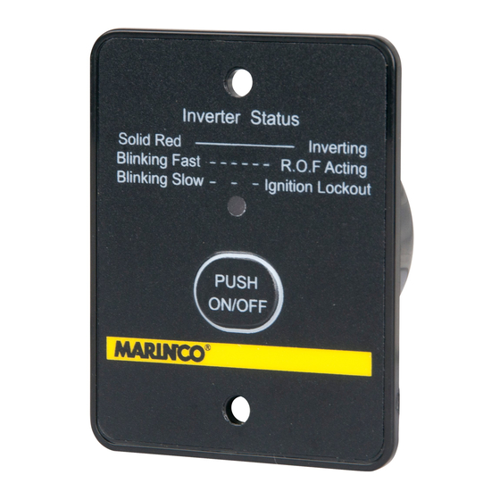
3-1. See Figure 1. The Inverter Status LED shows three modes of the Remote Control:
* Steady red LED light indicates the Inverter is ON.
* Fast flashing red LED light indicates that the Return Override Function is activated.
* Slow flashing red LED light indicates that it the Ignition Lockout Function is activated.
3-2. Open the remote controller by removing the two screws at the back of the housing.
3-3. The JUMPER is placed inside the remote controller and it activates either the
Return Override Function or Ignition Lockout Function
* Jumper "Open" –
* Jumper "Short" –
Please note that the default mode is OPEN (Return Override Function).
3-4. The AUX. +12V faston cable must carry +12V DC only and contain a 12 Volt 0.5A fuse.
3-5. Connect the wire RJ-11 to the remote port TO INVERTER.
3-6. Optional: install the 12V cable for the Ignition Lockout Function or Return Override Function.
* Ignition Lockout function – The Ignition Lockout Function turns the Inverter OFF when
+12 Volt is applied. Typical use: switching Off the inverter during engine starting.
* Return Override Function – The Return Override Function turns the Inverter ON when
+12 Volt is applied. Typical use: switching On the inverter together with the electrical system.
4. Installation Procedure
Check the contents of delivery: INVR-1 Remote panel, 7.5 m [82 ft] RJ-11 cable, user's manual.
4-1. Refer to the drawing (see Figure 2) for screw hole and cutout dimensions while fixing or
installing the remote control.
4-2. Use the RJ-11 cable to connect the INVR-1 remote control to the inverter.
4-3. Put the inverter main switch into position REMOTE. Refer to the inverter manual.
10.5 – 15.5 Vdc
0 – 40 °C, 32 - 104 °F
- 30 - 70 °C, -22 - 158 °F
< 40mA
All Marinco inverters
Inverting
Figure 1
Overview
plus wiring
Return Override Function
Ignition Lockout Function
RJ11
0.5A
.
+12V
+
-
Advertisement
Table of Contents

Related Manuals for marinco INVR-1


Summary of Contents for marinco INVR-1
- Page 1 +12 Volt is applied. Typical use: switching On the inverter together with the electrical system. 4. Installation Procedure Check the contents of delivery: INVR-1 Remote panel, 7.5 m [82 ft] RJ-11 cable, user’s manual. 4-1. Refer to the drawing (see Figure 2) for screw hole and cutout dimensions while fixing or installing the remote control.
- Page 2 Represented in the EU by: Mastervolt B.V. Address: Snijdersbergweg 93 1105 AN Amsterdam The Netherlands Herewith declares that the product: INVR-1 Remote Control is in conformity with the provisions of the following EU directives: • 2004/108/EC (EMC Directive) • 2011/65/EU (RoHS Directive)
Need help?
Do you have a question about the INVR-1 and is the answer not in the manual?
Questions and answers