
Summary of Contents for CAMBER ORTHROS MIS
- Page 1 ORTHROS MIS P E D I C L E S C R E W F I X A T I O N S U R G I C A L T E C H N I Q U E G U I D E...
- Page 3 TABLE OF CONTENTS Impor tant Information Approach Pedicle Preparation and Dilation Screw Inser tion Rod Inser tion Secure the Rod Screw Extension Removal Optional Techniques Removal Techniques Set Contents Additionally Available Notes CM-800-001 Rev K DECEMBER 2019...
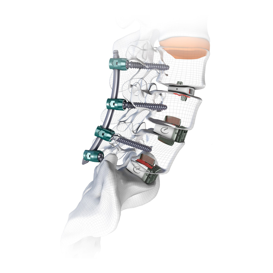
- Page 4 IMPORTANT INFORMATION DESCRIPTION The ORTHROS™ MIS Posterior Stabilization System consists of a variety of shapes and sizes of rods, monoaxial screws, polyaxial screws, locking caps, locking set screws, and associated manual surgical instruments. Implant components can be rigidly locked into a variety of configurations for the individual patient and surgical condition.
- Page 5 APPROACH The patient is administered anesthesia and placed in the prone position. The operative area is carefully cleaned and disinfected. Using C-Arm fluoroscopy, obtain an image to ensure patient spinous processes are aligned and that the vertebral body endplates are parallel to one another. INCISIONS The incision points will depend on the approach and technique of the user.
- Page 6 Remove the inner shaft of the Bone Aspiration Needle and discard, or unthread and remove the Cannulated Awl Trocar from the Cannulated Awl Handle. Select style and material K-wire (CM-130-01): Nitinol: Blunt, CM-130-01; Trocar, CM-130-02 Stainless Steel: Blunt, CM-130-03; Trocar, CM-130-04; Threaded, CM-130-05 Insert selected K-wire (CM-130-XX) to the desired depth while verifying using fluoroscopy.
- Page 7 Insertion Tip Succession of Etched Lines Repeat above incision technique for each pedicle. It is suggested to make all incisions prior to continuing on to pedicle preparation. CM-800-001 Rev K DECEMBER 2019...
- Page 8 PEDICLE PREPARATION & DILATION Insert the Cannulated Pedicle Probe (CM-129-01) over the K-wire (CM-130-XX). Twist the probe into the pedicle to open the pathway into the vertebral body. Use the succession of etched lines on the K-wire (CM-130-XX). The depth markings are etched in 15mm increments. Note the length of K-wire (CM-130-XX) protrusion through the handle of the Pedicle Probe (CM-129-01) and ensure that the K-wire (CM-130-XX) does not advance anteriorly during pedicle preparation.
- Page 9 Slide the 1-Step Dilator assembly over the K-wire (CM-130-XX) & gradually press into the incision. Once the 1-Step Dilator is touching the cortical wall of the pedicle, press the 1-Step Outer Dilator down further into the incision preparing for the Taps. Remove the 1-Step Inner Dilator prior to inserting the Taps.
- Page 10 If using the 3-Step Dilator process, insert Aluminum Dilator 1 (CM-119-07), followed by Aluminum Dilator 2 (CM-119-08) & Dilator 3 (CM-119-03) over the K-wire (CM-130- XX). Dilators 1 and 2 are also available in PEEK upon special request. TAPPING FOR THE PEDICLE SCREWS ORTHROS™...
- Page 11 Indicating The user may choose to undersize the Tap for the pedicle screw 55mm diameter selected. When using Ø5.5mm pedicle screws and the Pedicle user wants to undersize the Tap, a Ø5.0mm Tap is available in the Screw set. SCREW INSERTION Prior to implanting the pedicle screw, the user must identify the Insertion correct length of the screw selected.
- Page 12 SCREW INSERTION The selected pedicle screw should be removed from the module. Take the T25 MIS Polyaxial Screwdriver, ¼” Quick Connect (CM-117-02) & attach it to either the Straight Handle or the T-Handle. Pedicle Screws can be implanted through Dilator 3. Once the T25 Hexalobe Screwdriver Tip (CM-117-02) is seated in the bone screw, turn the outer dial clockwise, engaging the locking set screw thread.
- Page 13 If Dilator 3 was used, it should also be removed once the pedicle screws are implanted. Adjust the screw head position(s) with the Screw Head Positioner (CM-131-01) if needed. Orient screw heads as shown below to ensure easy rod implantation. ROD INSERTION DISSECTION The Ø5.5mm rods are all bullet-nosed to dissect tissue as the...
- Page 14 ROD LENGTH ESTIMATION The length of the rod can be estimated using the Rod Length Indicator (CM-137-02). Insert both shafts of the Rod Length Indicator into the most superior and inferior screws. The scale marked on the indicator’s caliper will estimate the rod length for the construct.
- Page 15 Find the Front Side indicator marking on the Rod Inserter. The rod engages the Rod Inserter from this side only. The rod will not lock to the Rod Inserter if loaded backwards. Once Front Side the rod is fully seated within the Rod Inserter, thread the dial Laser etched counterclockwise finger tight.
- Page 16 To verify the Rod is within each screw head, use the Rod Position Indicator (CM-137-01). The Rod Position Indicator has two bands around the shaft. If the band is above the screw head top surface, the rod is within the screw head. If you cannot see the band, the rod is not within the screw head.
- Page 17 SECURE THE ROD INSERT LOCKING SET SCREW Prior to releasing the Rod Inserter, the rod must be secured within each screw head. Ensure that the bulleted tip of the rod has clearly passed through the screw head prior to securing the rod to ensure proper construct locking.
- Page 18 FINAL TIGHTENING To final tighten or lock the pedicle screw construct, attach the T30 Screwdriver, ¼” QC (CM-117- 04) and assemble it to the 8.5 N-m Final Tightening Handle, Torque Limiting (CC-100-53). Select a Counter Torque to use the T30 screwdriver through: External Counter Torque (CM-132-03) or Counter Torque (CM-132-01).
- Page 19 SCREW EXTENSION REMOVAL If Compression/Distraction is desired, do not remove screw head extensions and see steps on page 21. The Connection Tab and Screw Head Extensions protruding from the incisions must be re- moved prior to completing the construct. First, the Connection Tab must be broken free of the Screw Head.
- Page 20 Rotate the Screw Head Removal Tool towards the center of the screw. Next, rotate the Screw Head Removal Tool away from the center of the screw. This order of rotation leaves the smoothest screw head surface. Repeat for both screw head extensions on every screw in the construct.
- Page 21 OPTIONAL TECHNIQUES COMPRESSION & DISTRACTION The user may choose to compress and distract upon the pedicle screws during or near the end of the surgery, depending on the technique deployed. Do not remove the extension tabs from the screw heads if compression or distraction is needed; only remove the connection tabs. To compress or distract, the following instruments will work together to effectively manipulate the construct: (2) Compression / Distraction Towers (CM-128-01)
- Page 22 To change the Adjustable Fulcrum head position, pull axially on the head and then rotate clockwise or counterclockwise. Use the diagrams below to correctly position the Adjustable Fulcrum and Compression/ Distractor Actuator for the desired effect. Compression Setup Distraction Setup Actuator on Top Fulcrum on Top Fulcrum on Bottom...
- Page 23 SCREW HEAD EXTENSION ALIGNMENT If necessary, the Extension Tab Ring (CM-002-03) can be used to realign the screw head extensions after the connecting tab is removed. The Extension Tab Ring mates with the cuts on each screw head extension and can be put on from either side of the screw head. If the user needs assistance to remove the Extension Tab Ring, use the K-wire (CM-130-01) Gripper (CM-102-02).
- Page 24 SET CONTENTS IMPL ANTS CM-002-10 MIS Locking Set Screw CM-008-01 Ø5.5mm MIS Straight Rod, 150mm Lg. CM-008-03 Ø5.5mm MIS Straight Rod, 300mm Lg. ORM-30C Ø5.5mm MIS Curved Rod, 30mm Lg. ORM-35C Ø5.5mm MIS Curved Rod, 35mm Lg. ORM-40C Ø5.5mm MIS Curved Rod, 40mm Lg. ORM-45C Ø5.5mm MIS Curved Rod, 45mm Lg.
- Page 25 ORM-130C Ø5.5mm MIS Curved Rod, 130mm Lg. ORM-135C Ø5.5mm MIS Curved Rod, 135mm Lg. ORM-140C Ø5.5mm MIS Curved Rod, 140mm Lg. ORM-5530 Ø5.5mm MIS Polyaxial Pedicle Screw, 30mm ORM-5535 Ø5.5mm MIS Polyaxial Pedicle Screw, 35mm ORM-5540 Ø5.5mm MIS Polyaxial Pedicle Screw, 40mm ORM-5545 Ø5.5mm MIS Polyaxial Pedicle Screw, 45mm ORM-5550...
- Page 26 CP-132-38 Rod Bender CP-132-41 Rod Holder CM-102-02 K-wire (CM-130-01) Gripper CM-103-02 Rod Inserter CM-117-02 T25 MIS Polyaxial Screwdriver, 1/4” QC CM-117-03 T30 Self-Retaining Screwdriver, 1/4” QC CM-117-04 T30 Screwdriver, 1/4” QC CM-119-07 Dilator 1, Aluminum CM-119-08 Dilator 2, Aluminum CM-119-03 Dilator 3 CM-119-04 Dilator Pusher...
- Page 27 CM-134-10 Tap Sleeve CM-134-11 Tap Sleeve, PEEK CM-136-01 Screw Tab Removal Tool CM-128-01 Compression/Distraction Tower CM-128-02 Adjustable Fulcrum CM-128-03 Compression/Distraction Actuator ADDITIONALLY AVAILABLE IMPL ANTS CM-008-02 Ø5.5mm MIS Straight Rod, 200mm Lg. CM-008-04 Ø5.5mm MIS Straight Rod, 400mm Lg. ORM-145C Ø5.5mm MIS Curved Rod, 145mm Lg.
- Page 28 ORM-6545L Ø6.5mm Cannulated MIS Polyaxial Pedicle Screw, 45mm Lg. Long Tower ORM-6550L Ø6.5mm Cannulated MIS Polyaxial Pedicle Screw, 50mm Lg. Long Tower ORM-6555L Ø6.5mm Cannulated MIS Polyaxial Pedicle Screw, 55mm Lg. Long Tower ORM-7530L Ø7.5mm Cannulated MIS Polyaxial Pedicle Screw, 30mm Lg. Long Tower ORM-7535L Ø7.5mm Cannulated MIS Polyaxial Pedicle Screw, 35mm Lg.
- Page 29 NOTES CM-800-001 Rev K DECEMBER 2019...
- Page 30 CM-800-001 Rev K DECEMBER 2019...
- Page 31 CM-800-001 Rev K DECEMBER 2019...
- Page 32 S E E I N S T R U C T I O N S F O R U S E ( I F U ) F O R I N D I C AT I O N S , C O N T R A I N D I C AT I O N S A N D WA R N I N G S . ORTHROS MIS...
Need help?
Do you have a question about the ORTHROS MIS and is the answer not in the manual?
Questions and answers