
Summary of Contents for CERATIZIT KOMflex
- Page 1 KOMflex precision spindle Operating instructions head cuttingtools.ceratizit.com Classification: Öffentlich...
-
Page 2: Table Of Contents
Automatic adjustment via NC cycle ................. 14 Emergency shutdown ......................15 If the KOMflex is in an active state, but does not receive any commands from the interface IF20, the head is deactivated after a timeout of 5 minutes and goes into standby mode......... 15 Possible scenarios in which an emergency shutdown may occur ............ - Page 3 Tool with cylindrical shank ....................18 7.4.4 Coolant ..........................19 Commissioning the KOMflex ......................20 Presetting equipment ......................20 Use of the KOMflex on the machine ..................22 8.2.1 Overview of the product range ..................22 8.2.2 Subprogram for defining the customer program ............22 8.2.3...
-
Page 4: Introduction
• If a fault arises which could affect the safety of the KOMflex precision spindle head, it must be shut down. Please contact the manufacturer. • Please note that the following causes may affect the operational safety of the KOMflex precision spindle head as well as the safety of persons working with it: o Improper use of the KOMflex precision spindle head. -
Page 5: Safety Information
Intended use The KOMflex precision spindle head is only intended for boring and boring out and over turning. The KOMflex must only be installed and operated in the machine tools intended for this purpose. The KOMflex precision spindle head is only to be used as intended for this purpose. -
Page 6: Ec Declaration Of Conformity
KOMflex precision spindle head Operating instructions V1.1 31.03.2021 EC Declaration of Conformity cuttingtools.ceratizit.com Classification: Öffentlich... - Page 7 KOMflex precision spindle head Operating instructions V1.1 31.03.2021 cuttingtools.ceratizit.com Classification: Öffentlich...
-
Page 8: Radio Approval
—Connect the equipment into an outlet on a circuit different from that to which the receiver is connected. —Consult the dealer or an experienced radio/TV technician for help. Changes or modifications made to this equipment not expressly approved by CERATIZIT USA, Inc may void the FCC authorization to operate this equipment. This device complies with part 15 of the FCC Rules. -
Page 9: Glossary
31.03.2021 Glossary KOMflex adjustment range The KOMflex can be adjusted between -0.25 mm and +0.25 mm in relation to the central position of the slide. Centre position definition The centre position (CP) is the central position of the slide (zero point). -
Page 10: Reinitialisation
Reinitialisation During reinitialisation, the KOMflex precision spindle head is reverted to its initial state. This means that the KOMflex travels to the VIP and the radius wear in the tool table is reset to 0. (See section 8.3) cuttingtools.ceratizit.com Classification: Öffentlich... -
Page 11: System Overview
• Any measuring unit, e.g. measuring probe The automatic KOMflex compensation system enables process-secure boring of holes and pins on a machine tool. The finished hole is measured with any measuring unit and compared to the target dimension. The precision spindle head then automatically corrects the set value deviation. To do so the dimension to be adjusted is transferred from the NC to the IF20 Interface via Ethernet or field bus. -
Page 12: Description Of The Rc66 Wireless Receiver
KOMflex mode In KOMflex mode, the MODE LED (1a) and the RX LED (1d) light up steady green and the BATTERY LED (1b) is inactive. The display indicators can be found in the following table. This mode can be activated with the SET_KOMFLEX_MODE command. -
Page 13: Pairing Mode
(1d, 1e) indicate that data is being transferred. Once a KOMflex has been successfully taught-in, the BATTERY and the STATUS LED (1b, 1c) flash green. If pairing fails, due to timeout or a problem with the data transfer or an incorrect device type, for... -
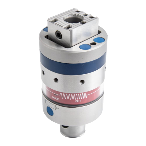
Page 14: Description Of The Komflex Precision Spindle Head
The automatic precision spindle head communicates with the BLUM RC66 wireless interface and forms a closed-loop operation (process, measure, correct, process) in conjunction with any measuring unit. Therefore, the KOMflex enables automatic diameter correction for precision holes. Technical data ABS 32 / Ø... -
Page 15: Komflex System Description
LED status (3x 120° = 360°) ⑪ Balance compensation Required accessories To operate the KOMflex in manual mode and to teach-in the precision spindle head on the machine tool, a magnetic pen or comparable magnet is required. Magnetic pen Magnet cuttingtools.ceratizit.com... -
Page 16: Description Of The Komflex Modes
To operate the KOMflex in manual mode, for example on the presetting equipment, the precision spindle head must be in standby mode (all KOMflex LEDs off). The user can then activate manual mode with a prolonged touch of the "MODE" sensor with the magnetic pen. When the magnetic pen is removed from the sensor and the LEDs change from yellow to orange, "Manual adjustment"... -
Page 17: Automatic Adjustment Via Nc Cycle
Successful teach-in of the precision spindle head is the prerequisite for automatic operation of the KOMflex, see section 8.2.4. In standby mode (all KOMflex LEDs off), "Automatic adjustment" mode can be activated via the computerised numerical control (CNC). In this state, the precision spindle head indicates the key statuses via flashing LEDs. -
Page 18: Emergency Shutdown
31.03.2021 Emergency shutdown If the KOMflex is in an active state, but does not receive any commands from the interface IF20, the head is deactivated after a timeout of 5 minutes and goes into standby mode. Possible scenarios in which an emergency shutdown may occur •... -
Page 19: Indicating The Basic Settings
(3 x MODE - SET) Standby Standard settings The KOMflex is always ready for re-activation in standby mode. If the KOMflex: Is outside the reception range of the wireless receiver, the system goes into EcoMode. Is within the reception range, it is always ready for re-activation. -
Page 20: Manually Configuring The Basic Settings
The basic settings can be changed in this mode. Note The magnetic pen is needed to operate the KOMflex in this section. 1. Remove the batteries. 2. After 30 seconds, re-insert the batteries in the battery compartment. Pay attention to the battery polarity. -
Page 21: Mounting
The balancing ring must not be clamped on the blue jacket or in the radio range. 7.4.2 Tools with ABS connection All existing ABS32 tools for fine machining can also be used in conjunction with the KOMflex precision spindle head. -
Page 22: Coolant
KOMflex precision spindle head Operating instructions V1.1 31.03.2021 7.4.4 Coolant The precision spindle head has a thro' coolant supply. Usage of the central coolant supply is mandatory and ensures optimal chip formation and chip removal. The coolant pressure must not fall below the minimum level of 5 bar. An increase in coolant pressure to 10-20 bar improves the machining process and should therefore be the aim. -
Page 23: Commissioning The Komflex
8 Commissioning the KOMflex Presetting equipment Before the KOMflex precision spindle head can be taught-in with the IF20 and therefore initialised, the VIP must be approached in manual mode, on the presetting equipment for example. This step always needs to be carried out if: •... - Page 24 KOMflex precision spindle head Operating instructions V1.1 31.03.2021 There are three ways of defining the VIP on the presetting equipment: ① Trial cut ② Without trial cut ③ Offset trial cut No correction through offset; Target diameter of the The VIP position is corrected by means...
-
Page 25: Use Of The Komflex On The Machine
KOMflex precision spindle head Operating instructions V1.1 31.03.2021 Use of the KOMflex on the machine 8.2.1 Overview of the product range Range Description Reference BKF_USERPARATABn Subprogram for defining the customer program Section 8.2.2 BKF_CONTROLLER Subprogram for NC ←→ IF20 communication... - Page 26 KOMflex precision spindle head Operating instructions V1.1 31.03.2021 The KOMflex tool data can also be defined in more detail in the BKF_USERPARATABn subprogram. The following table gives further information about the most important parameters. Definition of the tool data Parameter Meaning •...
-
Page 27: Parameter Overview When Calling Up Programs
Parameter Explanation KFID ID number with which teach-in was carried out for the KOMflex. Up to 16 KOMflex can be taught-in with an RC66. |1| <= KFID <= |16| The teach-in process can be skipped for an already taught-in KOMflex with negative KFID. -
Page 28: Teaching In The Komflex
8.2.4 Teaching in the KOMflex In this phase, a non-taught-in KOMflex can be taught-in in IF20 or an already taught-in KOMflex can be initialised. This means that the position of the head at the moment of teach-in is saved. If the precision spindle head used has already been taught-in on the machine and pairing is not to take place again, then this step can be skipped. -
Page 29: Correction In Automatic Mode
8.2.5 Correction in automatic mode In this cycle, the KOMflex is automatically readjusted in the process. To correct the measured value, the difference to the set value must be written in the wear parameter of the tool table for the relevant KOMflex, using measurement software. -
Page 30: Manually Switching Off
Reinitialisation of the KOMflex During reinitialisation, the KOMflex can move back to its original position, set during teach-in (position for a trial cut). This can be done manually in the case of an insert change or automatically if the wear limit is reached. -
Page 31: Extension Of The Machine With Further Komflex
31.03.2021 Extension of the machine with further KOMflex To integrate a new KOMflex into the machine, the program must be extended with a new BKF_USERPARATABn, whereby n is the KOMflex ID. This allows the system to be extended with ease, without losing clarity. -
Page 32: Changing The Cutting Edge
31.03.2021 Changing the cutting edge With the KOMflex system, the maximum wear limit for internal or external machining can be specifically adapted to the customer application via the _BKF_WEAR_LIMIT parameter in the BKF_USERPARATABn subprogram (section 8.2.2). If one of these values is dropped below or is exceeded, the program is stopped and the error message "Error E7 –... -
Page 33: Battery Replacement
KOMflex precision spindle head Operating instructions V1.1 31.03.2021 Battery replacement The KOMflex's batteries must be checked when: • The status LED flashes red or lights up red. • The error message 1117 – warning battery: battery voltage in critical state – appears on the CNC control. -
Page 34: Disposal Of Batteries
31.03.2021 8.6.2 Disposal of batteries The KOMflex precision head spindle must be disposed of in compliance with national and local regulations as part of the normal recycling process. Once it is no longer being used, statutory disposal regulations apply. In general, observe the following during disposal: Separate components for recycling into electronic waste, scrap iron, aluminium, plastic and battery. -
Page 35: Komflex Errors In Machine Operation
KOMflex precision spindle head Operating instructions V1.1 31.03.2021 KOMflex errors in machine operation Code Value Description of error 1100 Timeout: Position could not be reached in the specified time. 1102 Absolute VIP could not be set: Index outside range. Relative VIP could not be set: Index outside range. - Page 36 VIP cannot be set: Position detection is not available. 1110 Position could not be reached after the maximum number of position attempts. 1117 Battery warning: Battery voltage at a critical level. 1118 Incorrect status: KOMflex module is not ready. cuttingtools.ceratizit.com Classification: Öffentlich...
-
Page 37: Blum Errors In Machine Operation
KFID program parameter: KOMflex not taught-in |CALL WEAR_LIMIT| > 0.5 |MIN_DELTA| > 0.1 "Tool limits exceeded" Description: KOMflex correction value exceeds the permitted limit value. Solution: Correctly set _BKF_WEAR_LIMIT in USERPARATAB1 or in the call. Error number Digits after point... - Page 38 IF or EM not connected .02010 Error RC66 timeout .02011 Error RC66 "Manual intervention" Description: The KOMflex has been manually adjusted during automatic mode. Solution: Execute the BKF_REINITIALIZE program. Error number Digits after point Description of error Manual intervention "Incorrect tool/tool name"...
-
Page 39: Komflex Recycling - Our Recycling Service
KOMflex recycling – Our recycling service Our joint contribution to the environment - beyond the lifetime of the tool: We take back your used fine adjustment heads KOMflex and recondition them professionally. This saves you costs and effort for disposal.
Need help?
Do you have a question about the KOMflex and is the answer not in the manual?
Questions and answers