
Related Manuals for SANDIA aerospace SI-11X

Summary of Contents for SANDIA aerospace SI-11X
- Page 1 SI-11X Installation Manual 3700 Osuna Road NE Suite 711 905020-IM Albuquerque, NM 87109 www.sandia.aero Rev A...
- Page 2 This document and the information contained herein is the propriety data of SANDIA aerospace Corporation. No part of this document may be transmitted, reproduced, or copied in any form or by any means without the prior written consent of SANDIA aerospace.
-
Page 3: Table Of Contents
Table of Contents Section 1 - General Description ...........................4 Introduction ............................4 SI-11X Product Description .........................4 1.2.1 System Functions ..........................4 1.2.2 System Interfaces ..........................4 1.2.3 Unit Outer Dimensions ........................5 Specifications ............................6 1.3.1 Physical Characteristics ........................6 1.3.2 Electrical Characteristics ........................6 Environmental Characteristics ......................7 Section 2 - Installation Considerations ........................8... - Page 4 3700 Osuna Road NE Suite 711 Albuquerque, NM 87109 www.sandia.aero...
-
Page 5: Section 1 - General Description
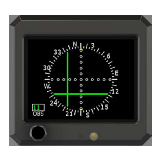
1.2 SI-11X Product Description The SI-11X Electronic Course Deviation Indicator is a panel mounted device to display lateral and vertical needles from a typical navigation receiver or GPS navigator. All information is displayed on a color 3.5” diagonal LCD display in traditional aerospace symbology. -
Page 6: Unit Outer Dimensions
1.2.3 Unit Outer Dimensions Figure 1 – Unit Outer Dimensions 3700 Osuna Road NE Suite 711 Albuquerque, NM 87109 www.sandia.aero... -
Page 7: Specifications
1.3 Specifications 1.3.1 Physical Characteristics Mounting ............Standard 3-1/8” Round Hole Overall Dimensions ...........3.52 x 3.22 x 1.84 in Bezel Dimensions..........3.52 x 3.22 x 0.50 in Weight ...............0.56 lbs (Including Bracket and Connector) Viewing Angle ..........60° Left/Right, 45° Up/Down Operating Temp ..........-20°C to +55°C Power Input ............10-32 VDC Current ..............1 Amp Max Power ............... -
Page 8: Environmental Characteristics
Environmental Characteristics Temperature .............-20 to 55 Degrees C Humidity ............DO-160G Standard Humidity, TBD Power ..............DO-160G Section 16, TBD EMI ..............TBD RFI ..............TBD 3700 Osuna Road NE Suite 711 Albuquerque, NM 87109 www.sandia.aero... -
Page 9: Section 2 - Installation Considerations
Section 2 - Installation Considerations 2.1 General The SI-11X interfaces to typical navigation receiver or GPS navigators via the standard analog that typically drove mechanical needle movements and flags. The resolver circuit in the SI-11X can also emulate electrically the mechanical resolver found in traditional mechanical CDI’s. -
Page 10: Section 3 - Installation Procedures
3.2 Equipment Required 3.2.1 Supplied SI-11X (Unit) ..........P/N 905020-00 Kit, Install Electrical SI-11X ......P/N TBD Conn, “D” 25 Pos, Rcpt, Sldr Cup .... P/N TBD Clamp, D Conn 45/180 Deg ...... P/N TBD Kit, Install Mechanical SI-11X ..... P/N 306187-00 Bracket, Mounting Front ...... -
Page 11: Required, But Not Supplied
24 AWG Shielded Twisted Pair. 3.3 Mounting Hole The SI-11X is designed to mount in a standard 3” round mounting hole. The supplied front mounting bracket (P/N 306179) and rear mounting bracket (P/N 306185) must be utilized to mount the instrument. -
Page 12: Wiring Installation
2. Keep power and ground lines less than 1 meter in length. The SI-11X is supplied with one 25 pin Sub-D female mating connector and back-shell. The Sub-D connector uses screw lock assemblies to secure the connector to the unit. The screw lock assemblies can be replaced with slide lock posts if desired by the installer. - Page 13 NAME DESCRIPTION VOR TO/FROM differential input. TO positive for TO indication P1-9 VOR TO Input at 40mV VOR TO/FROM differential input. FROM positive for FROM P1-10 Input FROM indication at -40mV VLOC VLOC LEFT/RIGHT differential. LEFT positive for left needle P1-11 Input LEFT...
-
Page 14: Unit Mounting
Figure 5 - Wiring Diagram 3.6 Unit Mounting 1. The unit connects to the mounting bracket utilizing two upper tabs and a lower fastener. 2. Place gasket on unit before installing unit onto bracket. 3. The unit is installed by engaging the two upper tabs first, then securing the bottom screw. 4. -
Page 15: Figure 6 - Unit Mounting With Tab/Slot Cutaway
Motion 1: Motion 2: Motion 3: Figure 6 - Unit Mounting With Tab/Slot Cutaway 5. Push the unit toward the instrument panel until it stops against the bracket. 6. While maintaining inward pressure, rotate the bottom such that the unit is now parallel to the panel. -
Page 16: System Configuration
3.7 System Configuration The following section provides instructions for initial setup configuration of the SI-11X Upon normal power-on, the unit will display the company logo, model number, part number and software version as follows: Figure 7 - Power On Screen After displaying the splash screen for approximately 7 seconds, the unit will enter the main operating mode. -
Page 17: Configuration Page
volatile memory. The Configuration Page display a yellow box in the upper left hand corner of the display. DO NOT CYCLE POWER WHILE THIS BOX IS DISPLAYED. Otherwise, a corruption of the non-volatile memory may occur and the unit will default it’s configuration. -
Page 18: Section 4 - Operation
3.7.3 Installation Adjustment The SI-11X needs to be adjusted to the navigation receiver or GPS navigator that it’s interfaced to. Many modern receivers have configuration pages that help in adjustment of the CDI. Garmin GNS4XX/5XX for example have a configuration page to drive the needles to Full Left, Right, Up and Down that can assist in the adjustment. - Page 19 3700 Osuna Road NE Suite 711 Albuquerque, NM 87109 www.sandia.aero...
Need help?
Do you have a question about the SI-11X and is the answer not in the manual?
Questions and answers