Table of Contents
Advertisement
Available languages
Available languages
Quick Links
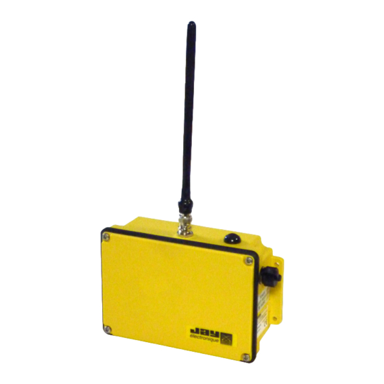
Répéteur radio actif sécurisé Jump
FR
Notice d'installation et d'utilisation (version originale) .................... page 03
Secure active radio repeater Jump
EN
Installation and user technical manual (translated from FR original
version) ........................................................................................... page 37
une société de / a company of
Jump
332970E_A005
Ref.doc. :
Advertisement
Chapters
Table of Contents

Subscribe to Our Youtube Channel
Summary of Contents for Conductix-Wampfler Jay Electronique Jump
- Page 1 Jump Répéteur radio actif sécurisé Jump Notice d’installation et d’utilisation (version originale) ....page 03 Secure active radio repeater Jump Installation and user technical manual (translated from FR original version) ................... page 37 une société de / a company of Ref.doc.
- Page 2 Jump - 332970E_A005 - 2 - 04/03/21...
- Page 3 Notice technique d’installation et d’utilisation Jump Répéteur radio actif sécurisé - version originale - - 3 - Jump - 332970E_A005 04/03/21...
-
Page 4: Table Of Contents
Table des matières Règles d’utilisation et précautions générales ........p. 5 Présentation du répéteur radio Jump ..........p. 6 Principe de fonctionnement ..............p. 7 Configuration ..................p. 10 4.1 Configuration à la livraison ................p. 10 4.2 Configuration du répéteur radio Jump ............p. 10 Antennes ....................p. 19 5.1- Gamme 433MHz................... p. 19 5.1- Gamme 915-920MHz. -
Page 5: Règles D'utilisation Et Précautions Générales
1 - Règles d’utilisation et précautions générales IMPORTANT : L’installateur doit bien prendre en compte le retard de traitement du répéteur Jump et l’additionner à la durée d’arrêt passif total du système. Voir chapitre «Principe de fonctionnement». Avant mise en service, il est indispensable de configurer le canal radio d’utilisation (réception) sur lequel le répéteur Jump devra fonctionner. Voir chapitre «Configuration». -
Page 6: Présentation Du Répéteur Radio Jump
2 - Présentation du répéteur radio Jump Nous vous remercions d’avoir choisi le répéteur radio actif sécurisé Jump. Le répéteur radio Jump est destiné à être utilisé avec les radiocommandes industrielles JAY Electronique des séries suivantes : - UD, UC, UR, RS (64 fréquences possibles, bandes 433MHz ou 915MHz) Il permet de conserver le niveau de sécurité de la chaine produits dans laquelle il est inséré. Le répéteur radio Jump intègre les concepts de sécurité... -
Page 7: Principe De Fonctionnement
3 - Principe de fonctionnement Le répéteur radio Jump est destiné aux solutions de radio-pilotage JAY Electronique à transmission monodirectionnelle. Le répéteur radio Jump permet de relayer un signal radio-électrique reconnu, sur un canal radio choisi par l’utilisateur. Le répéteur radio Jump apporte une solution pour les applications où il est nécessaire de franchir des environnements difficiles (obstacles, creux, bosses) qui ne permettent pas d’avoir une liaison directe, et également où... - Page 8 Exemple d’utilisation n°1 : Répéteur Jump Récepteur Equipement radio-piloté réception émission Emetteur réception émission : Fréquence radio, canal n°x Exemple d’utilisation n°2 : Installation Emetteur Fixe RSEF Si plusieurs JUMP fonctionnent sur la meme fréquence alors l’arrêt d’urgence du RSEF doit également couper de facon sûre l’alimentation de tous les JUMP.
- Page 9 Exemple d’utilisation n°3 : Répéteur Répéteur Jump 3 Jump 4 réception émission réception émission Récepteur Equipement radio-piloté réception Répéteur Jump 1 Répéteur Jump 2 réception émission réception émission émission : Fréquence radio, canal n°x Emetteur : Fréquence radio, canal n°y - 9 - Jump - 332970E_A005 04/03/21...
-
Page 10: Configuration
4 - Configuration 4.1 Configuration à la livraison Le répéteur radio Jump est configuré à la livraison avec les réglages suivants : Canal radio 64 (Roue A : 6, Roue B : 4) Niveau de puissance émission radio 4 (DIPswitch OFF-OFF-OFF) Choix du canal d’émission par rapport Canal d’émission radio = Canal de au canal de réception réception radio Nombre de trames répétées... - Page 11 4.2.1- Configuration du canal radio d’utilisation (réception) Le canal radio d’utilisation (réception) du répéteur Jump doit être le même que celui utilisé par le système de radio-pilotage. IMPORTANT : chaque répéteur Jump d’un équipement différent fonctionnant à proximité doit absolument être configuré sur un canal de fréquence différent. Pour les Séries UD, UC, UR et RS, 64 canaux radio sont disponibles (voir liste des fréquences en page suivante).
- Page 12 4.2.2- Liste des canaux et fréquences radio disponibles Fréquence (MHz) Fréquence (MHz) Canal Canal Bande 915 Bande 433 Bande 915 Bande 433 (UE) (USA/Canada) (UE) (USA /Canada) 433,100 911,800 433,900 915,100 433,125 911,900 433,925 915,200 433,150 912,000 433,950 915,300 433,175 912,100 433,975 915,400...
- Page 13 Fréquences (MHz) Fréquences (MHz) Canal Canal Bande 920 Bande 920 928,15 920,6 928,25 920,8 928,35 921,0 928,45 921,2 928,55 921,4 928,65 921,6 928,75 921,8 928,85 922,0 928,95 922,2 929,05 922,4 929,15 922,6 929,25 922,8 929,35 923,0 929,45 923,2 929,55 923,4 929,65 20mW (13dBm) 20mW (13dBm)
- Page 14 4.2.3- Configuration de la puissance d’émission radio Le répéteur Jump propose différents niveaux de puissance d’émission radio. L’ajustement de la puissance d’émission radio est sous la responsabilité de l’utilisateur, pour limiter ou adapter la portée en fonction de l’application et de l’autonomie souhaitée. Elle doit respecter la législation en vigueur dans le pays d’utilisation.
- Page 15 4.2.4- Choix du mode de fonctionnement (choix du canal émission entée) par rapport au canal de réception) 2 modes de fonctionnement radio sont disponibles. La sélection du mode s’effectue au moyen du DIPswitch «configuration» et du curseur n°5. TENS UNITS Position «ON» = MODE 2 CHARGE (canal émission ≠...
- Page 16 Mode 2 - gamme de fréquence 920MHz : système «Emetteur / réception JUMP et émission JUMP / Récepteur» sur deux canaux différents. Le signal reçu sur le canal n°x est réémis sur le canal n°y où y=x+1 Ce mode de fonctionnement permet d’utiliser plusieurs répéteurs au sein d’un couple «Emetteur / Récepteur». Attention : Seuls les canaux de 1 à 14 ou 16 à 30 sont disponibles Si le canal configuré est égal à n°15 ou supérieur à n°30 une erreur de configuration sera indiquée par la Led LD5.
- Page 17 4.2.5- Apprentissage du code d’identité de l’émetteur Le répéteur Jump ne peut fonctionner qu’avec un seul couple «Emetteur / Récepteur». Il est donc nécessaire de lui «apprendre» le code d’identité de l’émetteur. Le répéteur Jump ne garde en mémoire qu’un seul code d’identité. Pour cette procédure, le répéteur doit être sur le même canal radio que entée) l’émetteur.
- Page 18 4.2.6- Configuration du nombre de trames répétées. Le répéteur Jump propose différents choix de nombre de trames radio entée) répétées. La durée d’une trame radio est de 16ms. le nombre de trames doit être ajusté en fonction de la réactivité du système et la robustesse de la liaison L’ajustement du nombre de trames radio s’effectue au moyen du DIPswitch «configuration» par le biais des curseurs 6, 7. TENS UNITS CHARGE...
-
Page 19: Antennes
5 - Antennes 5.1- Gamme 433MHz. Référence antenne : VUA001A Type : droite, 1/4 d’onde, connexion BNC Longueur approximative : 190mm Référence antenne : VUA002A Type: droite, 1/2 d’onde, connexion BNC Longueur approximative : 335mm - 19 - Jump - 332970E_A005 04/03/21... -
Page 20: Gamme 915-920Mhz
5.2- Gamme 915-920MHz. Référence antenne : VUA001B Gamme de fréquence radio : 890-960 MHz Gain antenne : 1.5 dBi (besoin d’un plan de masse de 16x16cm) Type: droite, 1/4 d’onde, connexion BNC Longueur approximative : 82mm Référence antenne : VUA002B Gamme de fréquence radio : 890-960 MHz Gain antenne : 5 dB (comparé à 1/4 d’onde) Type: droite, 1/2 d’onde, connexion BNC... -
Page 21: Mise En Service Et Utilisation
6 - Mise en service et utilisation 6.1- Avertissement concernant le répéteur Jump. • Il y a un risque d’explosion si la batterie est remplacée par une batterie d’un type incorrect, seule la batterie réf.: PYB fournie par JAY Electronique est adéquate. • Seul le répéteur Jump version «batterie» est adapté pour recharger la batterie. -
Page 22: Alimentation
6.2- Alimentation Le répéteur Jump est disponible en 2 versions : - version «batterie» (batterie interne ref: PYB) - version «alimentation fixe» (alimentation par connecteur M12) Pour la version «batterie», un bouton poussoir ON/OFF est présent afin d’allumer et éteindre le répéteur. Lorsque le répéteur est éteint, la charge de la batterie s’effectue si une alimentation par câbles sur le connecteur M12 est présente. -
Page 23: Fonction Des Voyants Lumineux
6.3- Fonction des voyants lumineux Le répéteur Jump possède des voyants lumineux dont les fonctions et messages varient suivant la version du produit : 6.3.1- Jump version «Alimentation fixe» TENS UNITS CONFIGURATION CONFIG ERROR Voyant Couleur Fonction Etat Description Aucun signal radio reçu ou réception trames radio Eteint incorrectes Réception signal... - Page 24 6.3.2- Jump version «Batterie» Batterie PYB TENS UNITS CHARGE ERROR CONFIGURATION CONFIG ERROR Voyant Couleur Fonction Etat Description Eteint Pas d’erreur de charge batterie Erreur charge ROUGE batterie Erreur charge batterie (défaut électronique ou Allumé fixe températures de charge inadéquates) Aucun signal radio reçu ou réception trames radio Eteint incorrectes Réception signal...
- Page 25 6.3.3- Diagnostic d’anomalie Voyant Couleur Fonction Etat Description 1 à 6 clignotements erreur d’auto test synchrones LD2 + VERT + Indication d’un ROUGE défaut 7 clignotements code d’identité absent (voir chapitre «Apprentissage du synchrones code d’identité de l’émetteur») - 25 - Jump - 332970E_A005 04/03/21...
-
Page 26: Installation
7 - Installation 7.1- Fixation mécanique du répéteur Jump Jump 178 mm 60 mm 4 x Ø5.5 mm 7.2- Position physique du répéteur Jump Le répéteur radio Jump doit être placé à l’abri des chocs et des intempéries. Correct Correct Incorrect Correct Incorrect Armoire Armoire métallique métallique Les ondes UHF ne traversant pas les parois métalliques, l’antenne ne doit pas être placée dans une enceinte formant un blindage (armoire métallique, mur en béton armé, charpente ou paroi métallique, etc). -
Page 27: Option Commutateur Rf Vub095
8 - Option Commutateur RF VUB095 8.1- Description Cette option permet d’assurer une liaison radio continue dans un environnement RF encombré (réflexion, zones d’ombre ...) en commandant un commutateur RF pour transmettre les ondes radio à partir de deux antennes distinctes. Le commutateur RF VUB095 est piloté par le JUMP en concordance avec le nombre de trames configurées (cf §4.2.6). Ex : Si le nombre de trames répétées est configuré sur 6, le cycle de fonctionnement sera le suivant : Le JUMP écoutera pendant 100ms sur antenne1 Le JUMP émettra pendant 100ms sur antenne1 Le JUMP écoutera pendant 100ms sur antenne2 Le JUMP émettra pendant 100ms sur antenne2 IMPORTANT : La longueur maximale des câbles reliant le répéteur JUMP et le... -
Page 28: Caractéristiques Techniques
9 - Caractéristiques techniques Matière du boîtier PA6 chargé verre Couleur du boîtier Jaune (joint boitier noir) Protection IP IP65 Répéteur Jump version «Batterie» : 662g Masse Répéteur Jump version «Alimentation fixe» : 500g Version «batterie» : par batterie interne Li-ion 3,7V réf.: PYB, charge de la batterie par alimentation externe sur connecteur M12 (9-28VDC) / 6 W min Version «Alimentation fixe» : par alimentation externe sur connecteur M12 (9-28VDC) / 6 W min. -
Page 29: Paramètres Conformément À La Norme En 61508 Et En 62061
10 - Paramètres de sécurité 10.1- Essai réalisé Les essais ont été réalisés conformément aux principes d’essais. Les rapports détaillés sont conservés aux laboratoires d’essai. EN ISO 13849-1:2008 et EN 61508:2010 / EN 62061:2005 Des essais de fonctionnement, de simulation d’erreurs, l’examen du code source et des documents ont été... -
Page 30: Dimensions
11 - Dimensions (dimensions en mm) Jump - 332970E_A005 - 30 - 04/03/21... -
Page 31: Réglementation Fcc (Commission Fédérale Des Communications)
12 - Réglementation FCC (Commission fédérale des communications) Les intégrateurs OEM ont la responsabilité de s’assurer que l’utilisateur final n’a pas d’instruction pour retirer ou installer le module RF. Toutes modifications apportées à cet équipement non expressément approuvées par JAY Electronique peuvent causer des interférences nuisibles et annuler l’autorisation FCC d’utiliser cet équipement Cet équipement est conforme aux limites d’exposition aux rayonnements de la FCC définies... -
Page 32: Réglementation Ic (Industrie Canada)
13 - Réglementation IC (Industrie Canada) Les intégrateurs OEM ont la responsabilité de s’assurer que l’utilisateur final n’a pas d’instruction pour retirer ou installer le module RF. Cet équipement est conforme aux limites d’exposition aux rayonnements de la CNR102 applicables pour un environnement non contrôlé dans les conditions suivantes: 1. Cet équipement doit être installé et utilisé de telle sorte que la distance de séparation minimale de 20cm est maintenue à tout moment entre l’émetteur (antenne émission) et le corps de l’utilisateur. -
Page 33: Entretien
14 - Entretien Le boîtier du répéteur Jump doit être ouvert avec précaution (les vis du boîtier sont équipées d’un joint torique individuel à ne pas perdre). Si le joint du boîtier est abîmé, le matériel ne doit plus être utilisé jusqu’à remplacement de ces pièces d’étanchéité. Dans le cas contraire, tout liquide, toute poussière ou tout corps étranger peut endommager le répéteur Jump. L’attention de l’utilisateur est attirée sur les risques de l’utilisation du répéteur Jump dans un milieu comportant des solvants de polymères ou des colles pouvant dégrader son bon fonctionnement. -
Page 34: Garantie
16 - Garantie Tous nos appareils sont garantis 2 ans à partir de la date de fabrication indiquée sur le produit, hors pièces d’usure. Pour la batterie, la durée de garantie est limitée à 1 an. La réparation, la modification ou le remplacement d’un appareil pendant la période de garantie ne peuvent avoir pour effet de prolonger le délai de garantie. -
Page 35: Caractéristiques Environnementales
17 - Caractéristiques environnementales Etanchéité : le produit répond à la norme suivante: NF EN 60529 L’altitude n’affecte pas de manière significative les caractéristiques du répéteur actif sécurisé Jump jusqu’à 2000 m. Au-delà, il est nécessaire de tenir compte de la diminution de la rigidité diélectrique et du pouvoir réfrigérant de l’air (EN 60947-5-1). L’humidité relative ne doit pas dépasser 80% pour une température de +31°C max. Une humidité relative plus haute est possible pour des températures plus basses (ex: 90% pour +20°C). -
Page 36: Références Du Produit
21 - Références du produit Se référer à la documentation commerciale du produit 22 - Avertissement, évitez les perturbations mutuelles Vérifier que le système de transmission d’information sans fil ne dérange pas d’autres équipements/systèmes et qu’il n’est pas dérangé lui-même par d’autres équipements/systèmes. Utilisez des codes et des fréquences différentes. 23 - Limitation territoriale de l’utilisation du produit Voir ERC/REC 70-03 pour d’éventuelles limitations d’utilisation de l’annexe 1 Bandes F1 et F2 (Non-specific short range devices). 24 - Informations fabricant une société... - Page 37 25 - Déclaration CE de conformité DECLARATION DE CONFORMITE ORIGINAL Le fabricant : JAY électronique ZAC la Bâtie, rue Champrond 38334 ST ISMIER Cedex FRANCE Déclare que pour le Répéteur décrit dans la notice d’instructions, la déclaration de conformité s’applique aux appareils suivants : JUMP JUTxxxxx Est en conformité...
- Page 38 Test report issued under the responsibility of: Laboratoire EMITECH ANGERS MRA US-EU Designation Number: FR0009 FCC 47 CFR PART 15: 2018 ANSI C63.4: 2014 Company ......... : JAY ELECTRONIQUE Address..........: ZAC LA BATIE 37 ALLEE CHAMPROND 38334 SAINT ISMIER CEDEX - FRANCE FRANCE Test item description.
- Page 39 Test report issued under the responsibility of: Laboratoire EMITECH ANGERS IC Assigned Code: 4452A RADIO TEST REPORT ICES-003: 2016 ANSI C63.4: 2014 RSS-CNR GEN: 2014 Company ......... : JAY ELECTRONIQUE Address..........: ZAC LA BATIE 37 ALLEE CHAMPROND 38334 SAINT ISMIER CEDEX - FRANCE FRANCE Test item description.
- Page 40 Jump - 332970E_A005 - 40 - 04/03/21...
- Page 41 - 41 - Jump - 332970E_A005 04/03/21...
- Page 42 Installation and user manual Jump Secure active radio repeater - translated from FR original version - Jump - 332970E_A005 - 42 - 04/03/21...
- Page 43 Table of contents General safety rules ................p. 40 Overview of Jump radio repeater ............p. 41 Operating principle ................p. 42 Configuration ..................p. 45 4.1 Delivery configuration ................... p. 45 4.2 Configuration of Jump radio repeater ............p. 45 Antennas ....................p. 54 5.1- 433MHz Band....................p. 54 5.2- 911-918-920MHz band.
-
Page 44: General Safety Rules
1 - General safety rules IMPORTANT : When installing, be sure to take account of the 100ms processing delay which you must add to the total passive stopping time of the system. See «Operating principle» section. Before use, you must configure the radio channel on which the repeater will be operating. See «Configuration» section. It is essential to «learn»... -
Page 45: Overview Of Jump Radio Repeater
2 - Overview of Jump radio repeater Thank you for choosing our Jump secure active radio repeater. The Jump radio repeater is designed for use with the following series of JAY Electronique industrial radio remote controls : - UD, UC, UR, RS (64 possible frequencies, 433-434MHz bands and 915MHz bands) The Jump repeater is implemented to ensure the highest level of safety of the product line in which it is integrated. -
Page 46: Operating Principle
3 - Operating principle The Jump radio repeater is designed for use with the JAY Electronique radio control solutions implementing unidirectional transmission. The Jump radio repeater is used to relay a radio signal on a channel chosen by the user. The Jump radio repeater provides a solution for applications in difficult environments (obstacles, troughs, bumps) where a direct link is not possible, and in situations where radio performance must be extended to cover a greater distance or greater area. - Page 47 Example of use nb.1 : Repeater Jump Receiver Radio-controlled equipment recept. trans. Transmitter réception transmission : radio frequency, channel nb x Example of use nb.2 : Only for RSEF product and without using no-safe inputs If more then one JUMP are used on the same channel then RSEF emergency stop shall shut down the power supply of all JUMP.
- Page 48 Example of use nb.3 : Repeater Repeater Jump 3 Jump 4 recept. trans. recept. trans. Receiver Radio-controlled equipment reception Repeater Jump 1 Repeater Jump 2 recept. trans. recept. trans. transmission : radio frequency, channel nb x Transmitter : radio frequency, channel nb y Jump - 332970E_A005 - 48 - 04/03/21...
-
Page 49: Configuration
4 - Configuration 4.1 Delivery configuration The Jump radio repeater is configured on delivery with the following settings : Radio channel 64 (thumbwheel A : 6, thumbwheel B : 4) Radio transmit power level 4 (DIPswitch OFF-OFF-OFF) Choice of transmitting channel relative Radio transmission channel = Channel to the receiving channel radio reception... - Page 50 4.2.1- Configuration of radio channel The Jump repeater radio channel (reception) must be configured to the same channel used by the radio control system. IMPORTANT : each repeater Jump operating nearby must be absolutely configured with a different radio frequency channel. For the UD, UC, UR and RS series, 64 radio channels are available (see list of frequencies on next page).
- Page 51 4.2.2- List of channel and frequencies available Frequency (MHz) Frequency (MHz) Channel Channel 915 band 915 band 433 Band (UE) 433 Band (UE) (USA /Canada) (USA /Canada) 433,100 911,800 433,900 915,100 433,125 911,900 433,925 915,200 433,150 912,000 433,950 915,300 433,175 912,100 433,975 915,400...
- Page 52 Frequency (MHz) Frequency (MHz) Channel Channel 920 Band 920 Band 920,6 928,15 928,25 920,8 928,35 921,0 928,45 921,2 921,4 928,55 921,6 928,65 921,8 928,75 922,0 928,85 922,2 928,95 922,4 929,05 922,6 929,15 922,8 929,25 923,0 929,35 923,2 929,45 923,4 929,55 929,65 20mW (13dBm) 20mW (13dBm)
- Page 53 4.2.3- Configuration of radio transmit power The Jump repeater can be configured for different radio transmit power levels. The radio transmit power setting is defined by the user and is chosen to limit or adapt the range in accordance with the application and the desired endurance. It must respect the laws in force in the country where used.
- Page 54 4.2.4- Choice of operating mode (choice of transmission channel relative to the reception channel) Two radio operating modes are available. The choice of operating mode is performed using the DIPswitch «configuration» and cursor No. 5. TENS UNITS «ON» position = MODE 2 CHARGE (trans.
- Page 55 Mode 2 - 920MHz frequency range : «Transmitter / reception Jump and transmission Jump / Receiver» system operates with two different channels. The received radio signal on the radio channel No. x is retransmitted on channel No. y where y = x +1. This mode allows multiple repeaters with a « Transmitter / Receiver» pair. Caution : Considering the frequency jump performed, Only channels 1 to 14 or 16 to 30 are available If the configured channel is equal to n°15 or greater than n°30, a configuration error will be indicated by Led LD5.
- Page 56 4.2.5- Learning transmitter identity code The repeater Jump can only operates with a single «Transmitter / Receiver» pair. It is therefore necessary for the repeater to «learn» the transmitter identity code. The repeater Jump memory can only store one identity code. For this procedure, the repeater must be configured with the same radio channel as the transmitter.
- Page 57 4.2.6- Configuration of the number of frames repeated The Jump repeater can be configured for different repeat cycle. The duration of a radio frame is 16ms. The number of frames must be entée) adjusted in according to the system reactivity and the robustness of the radio link. The number of radio frames is adjusted using the DIPswitch «configuration»...
-
Page 58: Antennas
5 - Antennas 5.1- 433MHz Band. Antenna reference : VUA001A Type: straight, 1/4 wave, BNC connection Approximate length: 190mm Antenna reference : VUA002A Type: straight, 1/2 wave, BNC connection Approximate length: 335mm Jump - 332970E_A005 - 58 - 04/03/21... -
Page 59: 911-918-920Mhz Band
5.2- 911-918-920MHz band. Antenna reference : VUA001B Frequency Range: 890-960 MHz Antenna gain: 1.5 dBi (need grounded 16x16cm) Type: straight, 1/4 wave, BNC connection Approximate length: 82mm Antenna reference: VUA002B Frequency Range: 890-960 MHz Antenna gain: 5 dB (compared to 1/4 wave) Type: straight, 1/2 wave, BNC connection Approximate length: 190mm Antennas references :... -
Page 60: Commissioning And Use
6 - Commissioning and use 6.1- Warning regarding the repeater Jump • There is a risk of explosion if battery is replaced by a battery of an incor- rect type. Only battery ref.: PYB supplied by JAY Electronique is suitable. • Only the repeater Jump «battery» version is suitable for recharging the batteries. • Do not expose the battery to temperature above 50°C (122°F). •... -
Page 61: Power Supply
6.2- Power supply The Jump repeater comes in 2 versions : - a «battery» version (internal battery, ref: PYB) - a «fixed power supply» version (supplied by M12 connector) With the « battery » version, an ON/OFF pushbutton is provided to switch on and off the repeater. When the repeater is switched off, the battery is charged by a supply cable on the M12 connector. -
Page 62: Indicator Light Functions
6.3- Indicator light functions The Jump repeater has indicator lights with functions and messages defined according to product version : 6.3.1- Jump «Fixed power supply» version TENS UNITS CONFIGURATION CONFIG ERROR Color Function State Description No radio signal received or reception of incorrect frames Radio signal GREEN On steady Radio signal reception with correct frames... - Page 63 6.3.2- Jump «Battery» version Batterie PYB TENS UNITS CHARGE ERROR CONFIGURATION CONFIG ERROR Color Function State Description No battery charge error Battery charge error Battery charge error (Electronic fault or inappropriate On steady charging temperatures) No radio signal received or reception of incorrect radio frame Radio signal GREEN...
- Page 64 6.3.3- Troubleshooting Color Function State Description 1-6 synchronized self test error flashes LD2 + GREEN + Error indication 7 synchronized No identity code stored (see chapter «Learning the flashes transmitter identity code») Jump - 332970E_A005 - 64 - 04/03/21...
-
Page 65: Installation
7 - Installation 7.1- Mechanical mounting of Jump repeater Jump 178 mm 60 mm 4 x Ø5.5 mm 7.2- Physical position of Jump repeater The Jump radio repeater must be placed in a location which is sheltered from impacts and weather. Wrong Wrong metal metal cabinet cabinet RF waves do not cross metal walls. The antenna must not be placed in an enclosure forming a shield (metal cabinet, reinforced concrete wall, metal framework or wall, etc.). -
Page 66: Option Switch Rf Vub095
8 - Option switch RF VUB095 8.1- Description This option ensures a continuous radio link in a congested RF environment (reflection, shadow areas ...) by controlling an RF switch to transmit radio waves from two separate antennas. The VUB095 RF switch is controlled by the JUMP in accordance with the number of configured frames (cf §4.2.6). -
Page 67: Technical Characteristics
9 - Technical characteristics Housing material Fiberglass-charged PA6 Housing colour Yellow (black housing seal) IP protection IP65 Jump radio repeater «Battery» version : 662g Weight Jump radio repeater «Fixed power supply» : 500g «Battery» version : by internal battery Li-ion 3,7 V, ref.: PYB, charged by external power supply on M12 connector (9-28VDC) / 6 W min. «Fixed power supply» version : by external power supply on M12 connector (9-28VDC) / 6 W min. -
Page 68: Safety Parameters
10 - Safety parameters 10.1- Conducted test Tests according to the test principles were conducted. Detailed reports are held in the laboratories files. EN ISO 13849-1:2008 and EN 61508:2010 / EN 62061:2005 Function tests, error simulation, a review of the source code and documents are performed. The following parameters are calculated: EN ISO 13849-1:2008 MTTF... -
Page 69: Dimensions
11 - Dimensions (dimensions in mm) - 69 - Jump - 332970E_A005 04/03/21... -
Page 70: Fcc Rules & Regulations
12 - FCC Rules & Regulations (Federal Communications Commission) The OEM integrators are responsible for ensuring that the end-user has no manual instructions to remove or install module. Any changes or modifications to this equipment not expressly approved by JAY Electronique may cause, harmful interference and void the FCC authorization to operate this equipment This equipment complies with FCC’s radiation exposure limits set forth for an uncontrolled environment under the following conditions: 1. -
Page 71: Ic Regulations (Industry Canada)
13 - IC Regulations (Industry Canada) The OEM integrators are responsible for ensuring that the end-user has no manual instructions to remove or install module. This equipment complies with RSS102’s radiation exposure limits set forth for an uncontrolled environment under the following conditions: 1. -
Page 72: Servicing
14 - Servicing The Jump repeater housing must be opened carefully (the housing screws are equipped with an individual O-ring which should not be lost). If the housing seal is damaged, the unit should be removed from use until the seal is replaced. Failure to do so may result in liquid, dust or foreign matter getting into the unit and damaging the Jump repeater. -
Page 73: Warranty
16 - Warranty All our products are guaranteed two years as of date of product manufacture (indicated on product), excluding wear parts. For the battery, the warranty period is limited to 1 year. Repair, modification or replacement of a device during the warranty period may not have the effect of extending the warranty period. -
Page 74: Environmental Data
17 - Environmental data Tightness : product fulfils following standard: NF EN 60529 The altitude does not significantly affect the characteristics of the secure active repeater Jump up to 2000 m. At higher altitudes, it is necessary to take into account the reduction of the dielectric strength and the cooling effect of the air (EN 60947-5-1). The relative humidity must not exceed 80% for a temperature of +31 ° C max. A higher relative humidity is possible at lower temperatures (eg 90% to 20 ° C). The JUMP have to be protected of weather, U.V. and frost. -
Page 75: Products References
21 - Products references See the sales documentation of the product 22 - Warning, avoid any mutual disturbance Be certain that the wireless System doesn’t disturb other Systems and that it is not being disturbed itself by other Systems. Use different codes and different frequencies 23 - Countries limitation of the use See ERC/REC 70-03 for eventual limitation of the use of Annex 1 Bands F1 and F2 (Non-specific short range devices). -
Page 76: Ce Declaration Of Conformity
24 - CE declaration of conformity Translatd from French DECLARATION OF CONFORMITY The manufacturer JAY Electronique ZAC la Bâtie, rue Champrond 38334 ST ISMIER Cedex FRANCE Declares that for the repeater set described in its instructions, the declaration of conformity applies to the following devices: JUMP JUTxxxxx is in conformity with the requirements of the following directives and conformity was checked in accordance with the following standards:... - Page 77 Test report issued under the responsibility of: Laboratoire EMITECH ANGERS MRA US-EU Designation Number: FR0009 FCC 47 CFR PART 15: 2018 ANSI C63.4: 2014 Company ......... : JAY ELECTRONIQUE Address..........: ZAC LA BATIE 37 ALLEE CHAMPROND 38334 SAINT ISMIER CEDEX - FRANCE FRANCE Test item description.
- Page 78 Test report issued under the responsibility of: Laboratoire EMITECH ANGERS IC Assigned Code: 4452A RADIO TEST REPORT ICES-003: 2016 ANSI C63.4: 2014 RSS-CNR GEN: 2014 Company ......... : JAY ELECTRONIQUE Address..........: ZAC LA BATIE 37 ALLEE CHAMPROND 38334 SAINT ISMIER CEDEX - FRANCE FRANCE Test item description.
- Page 79 - 79 - Jump - 332970E_A005 04/03/21...
- Page 80 Jump - 332970E_A005 - 80 - 04/03/21...
- Page 81 support.technique.jay@conductix.com a company of ZAC la Bâtie, rue Champrond F38334 SAINT ISMIER cedex Tel: +33 (0)4 76 41 44 00 www.jay-electronique.com - 81 - Jump - 332970E_A005 04/03/21...
Need help?
Do you have a question about the Jay Electronique Jump and is the answer not in the manual?
Questions and answers